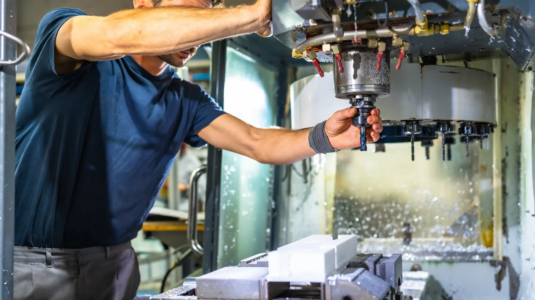
Home / Capabilities
Capabilities

Manufacturing Capabilities Built Around Your Part

CNC machining, molding, casting, forging, gear manufacturing and secondary operations coordinated through one engineering interface.

Multi-Process ManufacturingEngineering + Quality Coordination
Integrated manufacturing capabilities
How We WorkCNC MachiningMolding & ToolingPlanning GuideQualityCasting & ForgingValue Added
How We Work

One project interface across multiple manufacturing routes.

HSC manages engineering review, process matching, sourcing, quality follow-up and delivery, drawing on qualified manufacturing resources across the STI group and partner network.

HSC project interface

Engineering review & project management

We review drawings, identify process and quality requirements, build the manufacturing route and coordinate the project from RFQ through delivery.

  • One technical point of contact
  • DFM and process planning
  • Quotation, schedule and delivery coordination
Process-fit production

Manufacturing matched to the part

CNC machining, molding, casting, forging and specialist processes are selected around geometry, material, tolerance, volume and delivery requirements.

  • Process and equipment matched to the drawing
  • Prototype through repeat production
  • Specialist routes when needed
Quality & documentation

Inspection planned with production

Critical dimensions, inspection methods, reports and material or process documentation are defined before production and followed through final release.

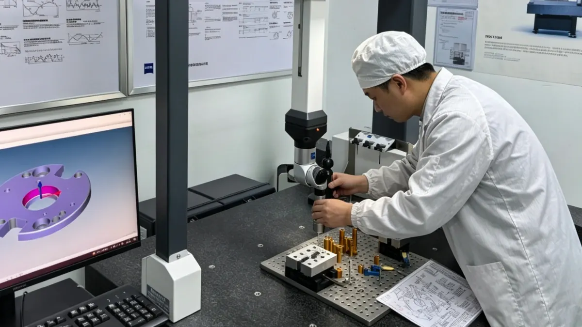
  • FAI, CMM and dimensional reporting
  • Material and process documentation
  • Traceability by project scope
Project planning: Final process, equipment, inspection scope and production site are confirmed against your drawing during quotation.
Core CNC Capability

CNC routes for complex geometry, precision features and repeat production.

Choose the process closest to your part. Our engineering team reviews machine fit, setup strategy, tolerance and inspection requirements before quotation.

Core milling capability

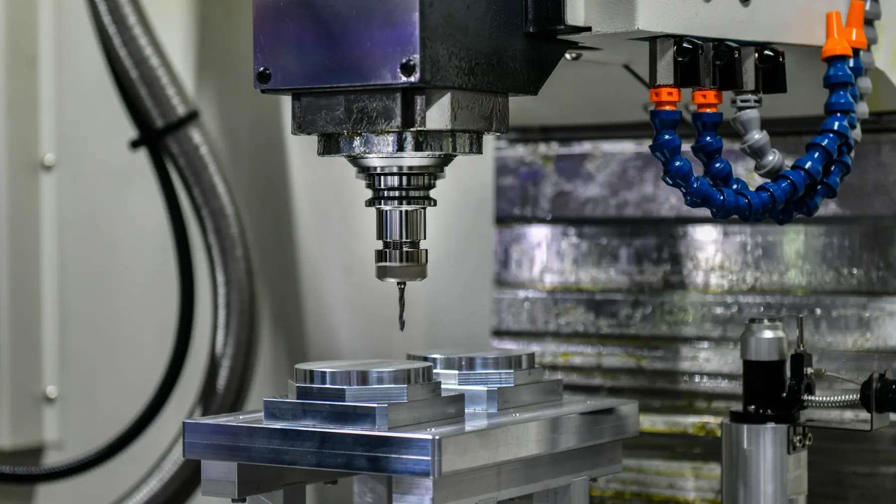
CNC Milling

3-axis, 4-axis, 3+2 and simultaneous 5-axis machining for prismatic, contoured and multi-surface parts.

  • Multi-axis machining and complex workholding
  • Large-format routes reviewed by part and fixture size
  • Probing and inspection planning for critical features
Explore milling →
Precision turning capability

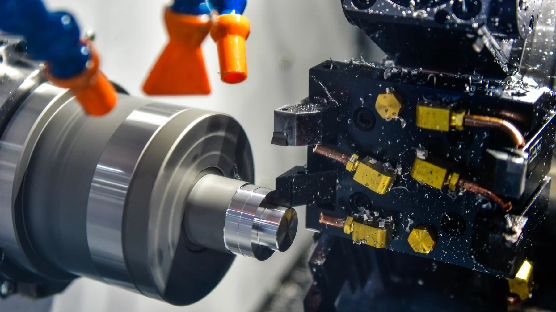
Swiss & Production Turning

Swiss-type, bar-fed and conventional CNC turning for pins, shafts, sleeves, bushings and repeat cylindrical components.

  • Live tooling and sub-spindles
  • Small-diameter bar work
  • High-mix and repeat batches
Explore turning →
Complex turning capability

Mill-Turn & Larger Turning

Y-axis, live-tool and sub-spindle routes for parts that combine turning with milled features.

  • Reduced secondary setups
  • Complex shafts, discs, flanges and housings
  • Chucking and support reviewed for runout and stability
Explore mill-turn →
Specialist machining capability

EDM & Grinding

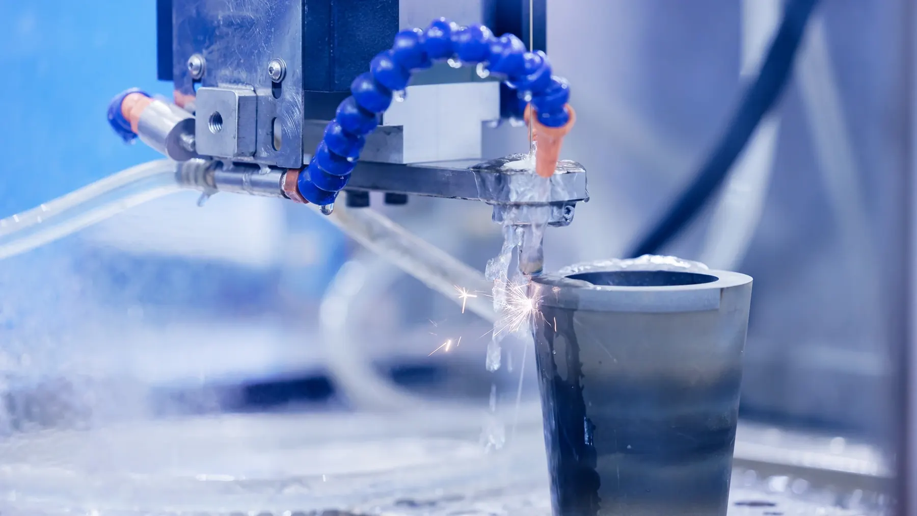
Wire, sinker and small-hole EDM plus grinding for hardened materials, narrow features and post-heat-treatment geometry.

  • Wire, sinker and small-hole EDM
  • Grinding and surface-integrity routes
  • Feature depth, access and finish reviewed by project
Explore EDM →
Drawing-led manufacturing plan

Precision Manufacturing

Machining, fixturing, datum strategy and inspection planned together for tight-tolerance or multi-setup parts.

  • CMM and GD&T inspection
  • FAI and dimensional reports
  • Critical-feature controls
Explore precision →
Specialist partner capability

Gear Components

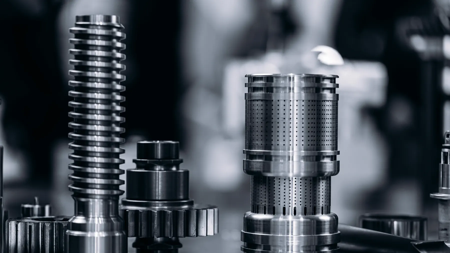
Shaping, hobbing and grinding for external or internal gears and splines, coordinated with material condition, heat treatment and inspection.

  • Gear shaping for internal / external gears and splines
  • Gear hobbing for spur and helical gears
  • Gear grinding for hard-finished accuracy
Explore gear projects →
Molding & Tooling

From DFM and tooling to molded-part production.

Injection molding projects can include mold design, tool build, trials, production, inspection and post-mold operations under one RFQ.

Tooling & molding capability

Tooling and molding matched to resin, geometry and annual volume.

Capabilities include DFM, mold-flow support, multi-cavity tooling, engineering resins, CMM inspection and coordinated assembly operations.

128–260T press range

Press selection is matched to projected area, shot weight, mold size and part requirements.

Tooling lifecycle

Rapid and production tooling, hot/cold runners, multi-cavity options, maintenance and controlled storage.

Quality-system support

ISO 9001 and ISO 13485 production-site options are available for suitable projects; applicability is confirmed with the selected route.

DFM-ledtolerance and tooling review
Multi-cavityvolume-scaled tooling options
Tool-lifetarget defined per project
1–2 daystypical initial RFQ response
Capability Planning Guide

Use the overview below to prepare an RFQ.

These process descriptions support early planning. Final feasibility is confirmed against the drawing, material, tolerance, quantity and documentation requirements.

Your quotation identifies the proposed process route, equipment class, inspection plan and project-specific limits.
Capability familyPlanning guideKey RFQ checks
CNC milling3-axis, 4-axis, 3+2 and simultaneous 5-axis routes; large-format machining availablePart envelope, axis strategy, tool access, fixture clearance and tolerance.
CNC turning & mill-turnStandard CNC turning, Y-axis/live-tool/sub-spindle mill-turn and Swiss-type routesBar capacity, chucking, support method, runout, setup count and batch plan.
EDM & grindingWire, sinker and small-hole EDM, with grinding available for suitable featuresWork envelope, feature depth, surface finish, recast-layer control and reporting.
Injection molding & tooling128–260T injection molding, toolmaking, overmolding and insert moldingPress selection, mold size, resin, projected area, shot weight, cosmetic standard and tool life.
InspectionCMM, GD&T, roughness, hardness and material-verification routesMeasurement method, calibration, sampling, report format and acceptance criteria.
Quality-system supportISO 9001 and ISO 13485 production-site options for applicable projectsCertificate scope and applicability to the selected manufacturing route and project.
Quality Assurance & Control

Quality planned before production. Verified before release.

HSC translates drawing, specification and customer requirements into a project-specific quality plan, then coordinates the selected production partner, inspection resources and required documentation through final release.

Project Quality Management

One quality plan across the selected manufacturing route.

Quality requirements are defined with the manufacturing plan rather than checked only at the end. Critical features, acceptance criteria, inspection methods, reporting and traceability are agreed before production starts.

Drawing ReviewControl PlanProduction ChecksFinal Release
Dimensional & GD&T InspectionCMM, gauges, height measurement, optical measurement and other suitable methods are selected according to feature, tolerance and reporting needs.
Material & Process VerificationMaterial certificates, heat-treatment records, surface-treatment documentation, hardness or other specified evidence can be included in the project package.
First Article & Sample ApprovalFAI, dimensional reports, golden samples or customer-specific approval formats can be defined before production release.
Traceability & RecordsLot identification, inspection records, process documentation and part marking are coordinated when the project requires traceability.
NDT & Special TestingPT, MT, UT, X-ray, leak, functional or other project-specific testing can be coordinated where technically applicable and included in the agreed scope.
Customer Quality PackagesCoC, PPAP, SPC, MSA, NCR/8D and other customer-defined documentation can be planned where required by the project.
01

Requirement & risk review

Identify critical dimensions, datums, GD&T, material, cosmetic, functional, compliance and documentation requirements before quotation release.

02

Production & inspection alignment

Match the manufacturing route with suitable production and inspection resources, then confirm control points, equipment and applicable quality-system scope.

03

In-process & first-article control

Coordinate FAI or sample approval, in-process checks, critical-feature controls and traceability according to project risk and production volume.

04

Final verification & release

Confirm agreed inspection results, required certificates and reports, packaging requirements and final release status before shipment.

Inspection and testing may be performed at the selected production site or through qualified metrology and testing resources, depending on the requirement. HSC coordinates the agreed scope and consolidates the required quality records for the project.

Casting & Forging

Casting and forging routes for strength, geometry and production-volume requirements.

Review die casting, specialty polymer casting and forging options, including downstream machining, finishing and inspection.

Process selection

Compare process fit before committing to tooling or blank production.

The dedicated process page explains route selection, typical applications, machining integration and RFQ requirements for cast and forged parts.

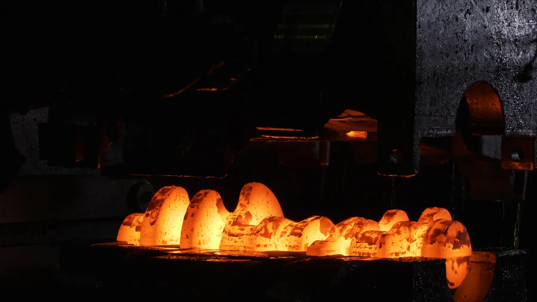
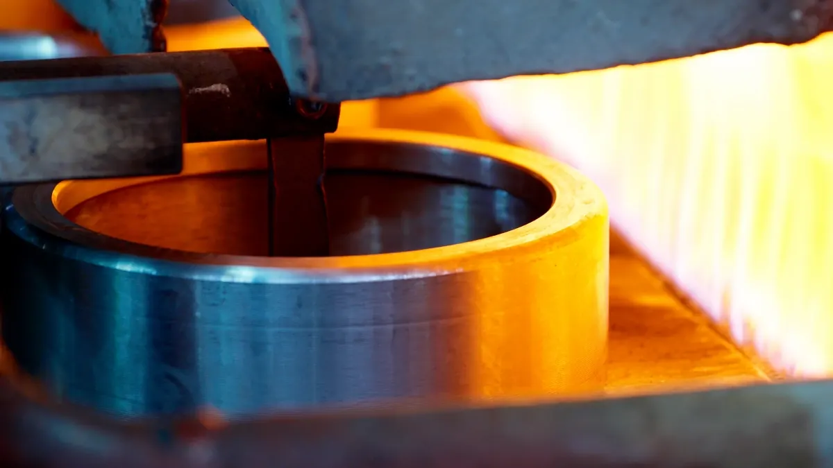
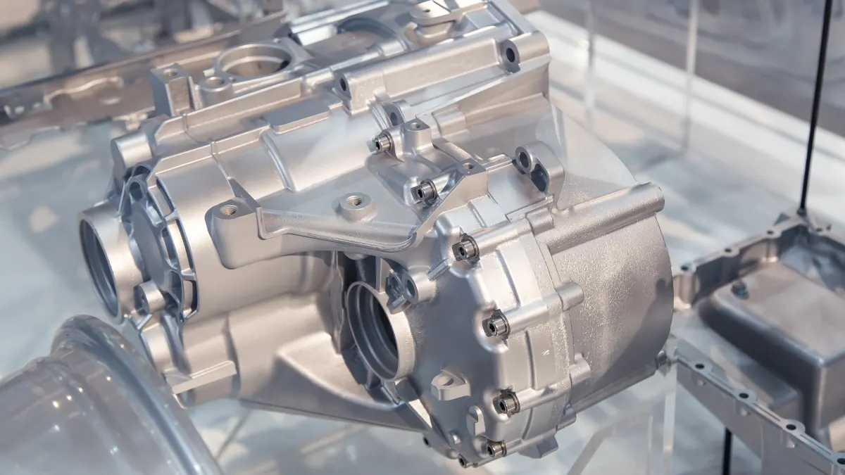
Casting and forging industrial manufacturing
Value Added

One RFQ beyond the primary manufacturing process.

HSC coordinates secondary processing around CNC machining, molding, casting, forging and other primary routes so finish, function, inspection, assembly and delivery requirements stay aligned under one project interface.

Deburring & edge condition

Deburring, edge break, polishing, tumbling and drawing-specified edge conditions coordinated to protect functional and cosmetic requirements.

Surface finishing

Anodizing, plating, passivation, blasting, painting, coating and other specified surface treatments matched to material and application.

HT

Heat treatment

Quenching, tempering, aging, stress relief, carburizing, nitriding and other specified treatments coordinated with downstream dimensional requirements.

+

Inserts & hardware

Thread inserts, press-fit hardware, bushings, pins and other simple mechanical integration can be included where required by the assembly.

Marking & traceability

Laser marking, engraving, labels, serialization and customer-defined identification coordinated with drawing and traceability requirements.

Assembly, kitting & packaging

Simple assembly, kitting, protective packaging, part separation and export-ready preparation can be integrated into the delivery plan.

Coordinated Delivery

Keep secondary operations connected to the original drawing and quality plan.

HSC coordinates handoffs between the selected production, finishing, treatment, assembly and inspection resources, helping keep revision status, critical surfaces, masking requirements, acceptance criteria and documentation consistent from the primary process through shipment.

Primary ManufacturingSecondary ProcessingVerificationAssembly & PackagingShipment

Available secondary operations depend on material, specification, part geometry, order volume and the selected manufacturing route. Required finishes, standards, certificates, masking zones and cosmetic criteria should be included in the RFQ for confirmation.

Send one technical package. Receive one coordinated manufacturing plan.

Upload CAD, 2D drawings, material, quantity, tolerance, finish and inspection requirements. Our engineering team will review the project and recommend a suitable manufacturing route, quality plan and lead-time approach.

Upload CAD Package
Home / Capabilities / Casting & Forging
Casting & Forging

Casting & Forging From Blank to Finished Component.

HSC coordinates casting and forging programs through qualified manufacturing partners, with process selection, tooling, secondary machining, heat treatment, inspection and delivery managed through one project interface.

Qualified Manufacturing PartnersTooling & Secondary OperationsQuality Control & Inspection

From process selection to production delivery, HSC manages the complete manufacturing route.

Casting and forging industrial manufacturing
From process selection to finished supplyPartner matching, tooling, production, machining and inspection
Explore this page
Service Overview

Choose the manufacturing route from the part—not from a fixed factory process.

HSC reviews the drawing, material, mechanical targets, annual demand and downstream requirements first, then matches the project to the appropriate casting or forging route and qualified production partner.

Project Approach

One RFQ can cover the blank, secondary operations and final inspection.

Instead of forcing every project into one production site, HSC coordinates the manufacturing route around the technical and commercial requirements of the part.

Drawing-led route selection

Geometry, material, load path, tolerance, surface requirements and quantity are reviewed before the process is fixed.

Partner & equipment matching

The foundry, casting specialist or forge shop is selected according to the required process, tooling, production scale and quality scope.

Finished-part coordination

Machining, heat treatment, finishing, inspection, documentation and packaging can be managed within the same project scope.

Cast / Forgeroute selected by part requirement
Blank → Finishsecondary operations coordinated
FAI / NDTinspection scope by project
One RFQone HSC project interface
01

Die Casting

Repeat non-ferrous production where dedicated tooling, cycle efficiency and near-net geometry support the program economics.

  • Aluminum and zinc components for suitable applications
  • Tooling, machine class and production site confirmed during quotation
  • Machining, coating and dimensional inspection can follow casting
02

Specialty Polymer Casting

Low-volume urethane, silicone and vacuum-casting routes for prototypes, bridge production and selected flexible applications.

  • Lower tooling commitment than production injection molding
  • Material and mold-life expectations confirmed by project
  • Best suited to low-volume replication and validation programs
03

Hot, Cold & Precision Forging

Forging routes for structural and repeat-production components where material flow and mechanical performance are key design drivers.

  • Hot forging for substantial deformation and robust blanks
  • Cold forging for suitable compact, repeat geometries
  • Precision / near-net forging where reduced machining stock is valuable
04

Finished Component Supply

Coordinate the primary forming process with the downstream operations required to release a finished part.

  • CNC machining and datum control
  • Heat treatment, surface preparation and coating
  • Inspection, documentation, assembly and packaging where required
Production-site confirmation: Equipment, tooling route, process limits, quality-system scope and available inspection resources are confirmed against the selected manufacturing partner during quotation.
Casting Routes

Separate metal die casting from low-volume polymer replication.

These routes share the word “casting,” but their materials, tooling logic, volumes and performance expectations are different. HSC confirms the correct route before quotation release.

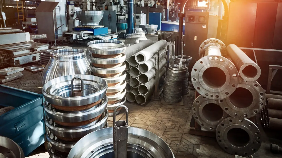
Cast components for industrial applications
Process classification: Die casting is a molten-metal production process. Urethane casting, silicone casting and vacuum casting are specialty low-volume polymer replication routes and should not be treated as equivalent foundry processes.
Metal Casting

Die Casting

A production route for repeat non-ferrous parts where dedicated tooling is justified by volume, repeatability and cycle efficiency.

  • Typical candidates include housings, brackets, covers and structural enclosures.
  • Key RFQ inputs: alloy, annual demand, cosmetic requirements, machining allowance and critical dimensions.
  • Secondary CNC machining, deburring, coating and inspection can be included in the project scope.
Machine class, mold plan and responsible production site are confirmed during quotation.
Low-Volume Polymer Casting

Urethane Casting

A practical replication route for prototypes and bridge-production parts that need production-like appearance without hard production tooling.

  • Useful for housings, covers, product shells and functional prototype parts.
  • Good fit for low quantity, fast iteration, color or texture requirements and reduced tooling commitment.
  • Material selection is confirmed against mechanical, cosmetic and application requirements.
Specialty casting partner, mold approach and expected mold life are confirmed during RFQ review.
Flexible / Elastomer Route

Silicone Casting

For selected flexible, soft-touch, sealing or prototype applications where silicone behavior is more important than rigid structural strength.

  • Typical uses include seals, pads, protective parts and low-volume custom shapes.
  • Hardness, temperature resistance, color and surface expectations should be defined in the RFQ.
  • Tooling and process route depend on geometry, quantity and the exact material specification.
Material grade and production method are confirmed before quotation is finalized.
Prototype Replication

Vacuum Casting

A low-volume route commonly used to replicate master patterns in polyurethane-like materials for design validation, market testing and bridge production.

  • Useful where CNC machining or hard injection-mold tooling would be excessive for the required quantity.
  • Well suited to appearance models, functional prototypes and small pilot batches.
  • Dimensional expectations and material behavior are reviewed against the intended application.
Master pattern, mold life, quantity and achievable finish are confirmed per project.
Forging Routes

Forging selected around material flow, mechanical performance and production economics.

Tooling, billet condition, heat treatment, machining allowance and final inspection are planned together because each affects the finished component.

Forging

Hot Forging

Metal is formed at elevated temperature to support substantial deformation and robust mechanical performance for industrial components.

  • Typical parts include shafts, flanges, yokes, arms, hubs and structural blanks.
  • Common downstream scope includes heat treatment, shot blasting, CNC machining and inspection.
  • Important RFQ inputs include alloy, target properties, annual quantity and final machined geometry.
Forge shop, billet route, tooling and heat-treatment plan are confirmed during quotation.
Forging

Cold Forging

A lower-temperature forming route for selected parts where material flow, repeatability and surface condition can justify dedicated tooling.

  • Typical candidates include fastener-like parts, pins, compact formed components and high-volume hardware.
  • Suitable geometries can benefit from material efficiency and reduced downstream machining.
  • Feasibility depends strongly on alloy, deformation ratio, geometry and tooling design.
Cold-forging suitability is confirmed from the drawing, material and expected production volume.
Near-Net Forging

Precision Forging

A higher-control forging approach intended to bring the blank closer to final geometry and reduce machining stock when program economics support it.

  • Useful for repeat components where forged geometry can reduce material removal.
  • Often evaluated together with heat treatment, machining datum strategy and inspection planning.
  • Tooling cost, expected volume and final tolerance requirements are key selection factors.
Achievable forged geometry, tolerance and machining allowance are confirmed during technical review.
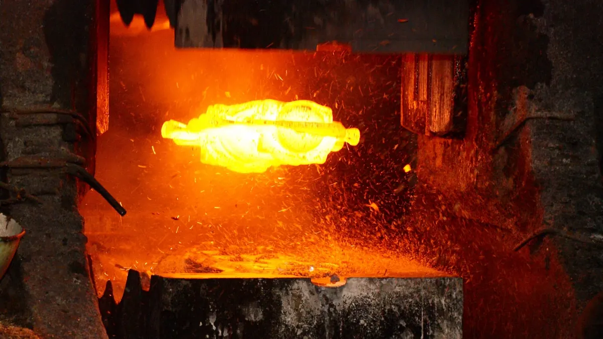
Hot forging production process
Forging Integration

Forged blank or finished component.

HSC can coordinate a forging-only scope or a broader package including heat treatment, CNC machining, surface preparation, inspection and delivery-ready packaging.

Process Comparison

Die casting or forging for a metal component?

Use this as an early planning guide. Final selection depends on part geometry, alloy, load path, mechanical targets, tolerance, tooling economics and annual demand.

Metal-process decision guide

Specialty polymer casting is intentionally excluded from this table because it serves a different low-volume replication use case.

Decision factorDie CastingForging
GeometryStrong for thin walls, integrated features and near-net non-ferrous shapes where die access allows.Strong for structural forms that can follow material flow and be finish-machined where needed.
Mechanical performanceAlloy- and process-dependent; suitable for many structural and enclosure applications.Often preferred when strength, fatigue resistance or impact performance is a dominant requirement.
Material profileCommonly non-ferrous alloys such as aluminum or zinc for suitable programs.Commonly carbon, alloy, stainless and other forgeable metals depending on the application.
Tooling economicsDedicated die investment is typically justified by repeat volume and part complexity.Closed-die and precision forging can also require significant tooling commitment.
Downstream workMachining, deburring, coating and inspection as required.Heat treatment, blasting, straightening, machining and inspection as required.
Best starting questionDoes near-net geometry and repeat production justify die tooling?Do mechanical performance and material flow justify a forged blank?
Secondary Operations

Coordinate the formed blank with the operations needed to release a finished part.

HSC can include downstream processes in the same RFQ so machining datums, heat-treatment effects, surface requirements and inspection criteria are considered from the beginning.

CNC

Machining

  • Datum establishment and machining allowance review
  • Milling, turning, drilling, tapping and precision interfaces
  • Inspection strategy linked to final machined features
HT

Heat Treatment

  • Project-specific hardening, tempering or other required thermal routes
  • Allowance for distortion and post-treatment machining where needed
  • Hardness or property evidence included to agreed scope
FIN

Surface & Finishing

  • Blasting, deburring and surface preparation
  • Coating, plating or painting where compatible with the material and application
  • Cosmetic zones and acceptance standards defined before release
ASSY

Assembly & Packaging

  • Hardware installation and simple assembly where required
  • Kitting, labeling and customer-specific packaging
  • Export and repeat-order documentation coordinated with shipment
Quality & NDT

Inspection scope matched to the failure risk of the part.

Quality planning starts with the drawing and application. The selected production site and inspection resources are confirmed before the project is released.

Casting & forging control plan

Control the material, blank, secondary operations and final dimensions as one chain.

Where required, the project can include material traceability, first-article inspection, dimensional reporting, mechanical-property evidence and non-destructive testing.

MaterialFormingSecondary OpsFinal Release
Material & traceabilityMaterial certificates, heat / lot traceability and required property records can be coordinated to the agreed scope.
Dimensional inspectionFirst-article, dimensional or CMM reports can be supplied where required by the drawing or project quality plan.
Mechanical checksHardness and other specified property evidence are coordinated when applicable to the selected material and process.
Non-destructive testingPT, MT, UT or radiographic / X-ray inspection can be arranged where technically appropriate and available at the selected production site.
Inspection applicability: NDT method, sampling level, acceptance criteria, certificate scope and reporting format must be defined by the project requirement and confirmed with the responsible production partner before order release.
How HSC Manages the Project

One customer interface across multiple specialized production routes.

HSC remains the coordination point while the responsible manufacturing partner performs the actual casting, forging and agreed secondary operations.

01

RFQ & Drawing Review

Review geometry, material, quantity, mechanical targets, tolerances, finish, inspection and delivery requirements.

02

Route & Partner Match

Select the appropriate casting or forging process and match the project to a qualified production partner with the required tooling and inspection capability.

03

Sampling & Validation

Coordinate tooling, first samples or FAI, dimensional results, corrective actions and customer approval before repeat production where applicable.

04

Production & Delivery

Follow production status, quality records, secondary operations, packaging, documentation and shipment through one HSC project channel.

FAQ & RFQ

What should you send for a casting or forging quotation?

A complete technical package allows HSC to compare process routes and production partners more accurately.

Which process should I choose if I am unsure?

Send the drawing and application requirements. HSC can compare suitable casting or forging routes based on geometry, material, quantity, mechanical targets and downstream operations.

Can the quotation include machining after casting or forging?

Yes. The RFQ can cover blank production together with CNC machining, heat treatment, finishing, inspection, assembly and packaging where required.

How is the production partner selected?

HSC matches the project to a qualified foundry, specialty casting partner or forge shop according to process fit, equipment, tooling, quality scope, volume and delivery requirements.

What quality documents or NDT can be included?

Material certificates, dimensional reports, hardness or property evidence and applicable NDT can be included when specified and confirmed with the selected production site.

Send one technical package. HSC coordinates the right route.

Upload CAD, 2D drawings, material, quantity, mechanical requirements, tolerance, finish and inspection scope. HSC will review the project and coordinate the quotation with the appropriate manufacturing partner.

Home / Capabilities / CNC Machining Services
CNC Machining

CNC Machining Services

CNC milling, turning, mill-turn, EDM and precision inspection for prototypes, low-volume parts and repeat production.

DFM & process planning3–5 axis machiningNDA availableEnglish project support

From prototype and first article through repeat production, process, equipment and inspection are matched to part geometry and drawing requirements.

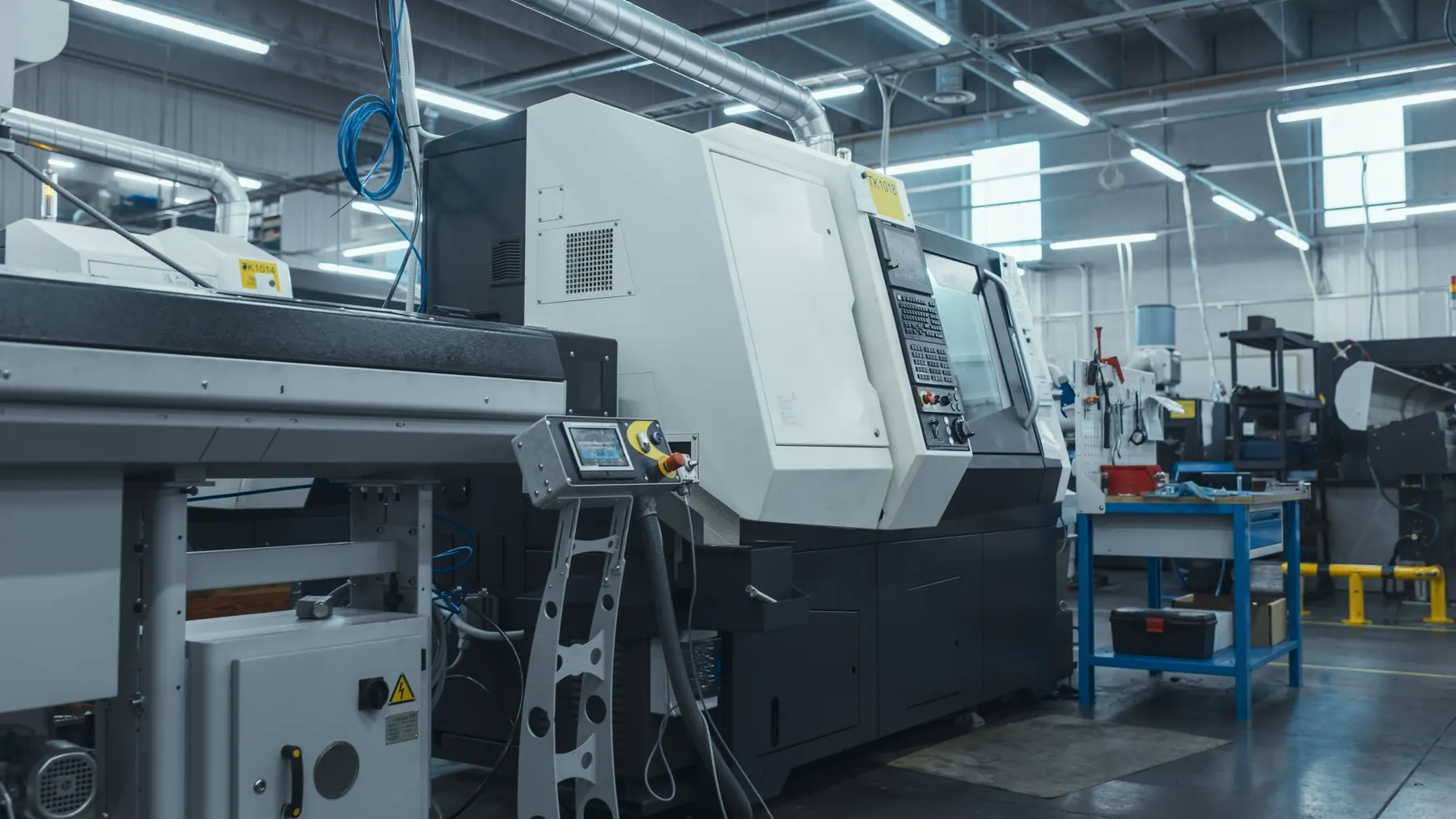
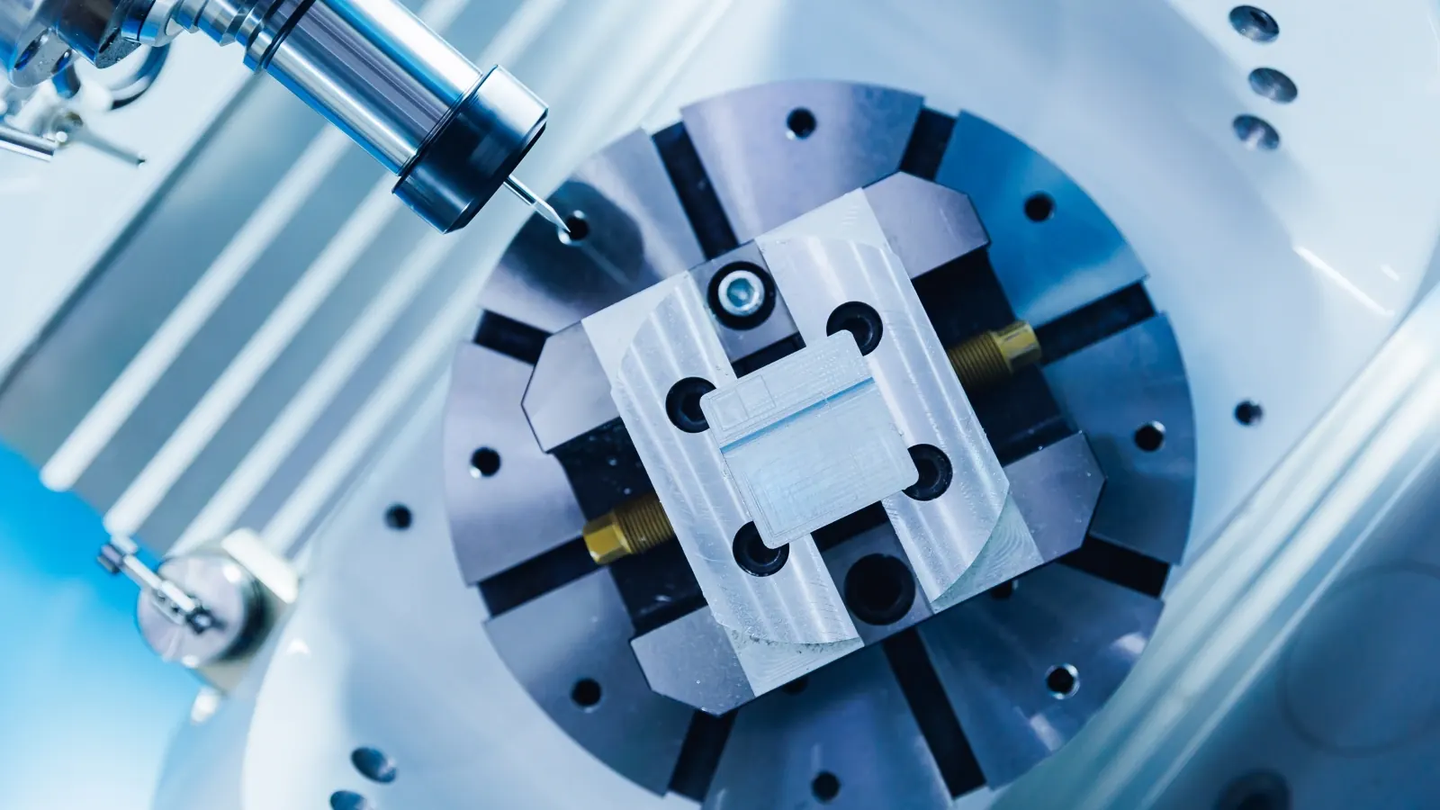
CNC machining page hero
Drawing-led manufacturingDFM • machining • inspection
Explore this page
Service Overview

CNC machining for complex geometry, critical features and repeat production.

Supported routes include multi-axis milling, turning, mill-turn, EDM, grinding and CMM inspection.

Engineering Approach

Plan machining, setup and inspection as one process.

Our engineering team reviews machine envelope, datum strategy, tool access, material, tolerance, quantity, finishing and inspection before the production route is released.

Complex milling

Multi-axis and large-format machining routes are selected around part geometry, workholding, tool access and critical features.

Turning & mill-turn

Standard turning, Swiss-type and live-tool mill-turn routes are matched to rotational geometry and setup requirements.

Inspection planning

CMM and other measurement methods are selected around drawing datums, critical dimensions and reporting needs.

3–5 axismilling routes
Mill-turnlive-tool & sub-spindle
EDMwire, sinker & small-hole
CMMdimensional & GD&T inspection
01

CNC Milling

For prismatic, contoured and multi-surface parts.

  • 3-axis, 3+2, 4-axis and simultaneous 5-axis
  • Complex workholding and multi-face machining
  • Large-format routes reviewed by part and fixture size
02

CNC Turning & Mill-Turn

For shafts, sleeves, flanges and complex rotational parts.

  • Standard CNC and Swiss-type turning
  • Y-axis, live tooling and sub-spindle routes
  • Chucking and support strategy reviewed for runout and stability
03

EDM & Grinding

For hardened materials, narrow features, deep holes and post-heat-treatment geometry.

  • Wire, sinker and small-hole EDM
  • Hardened and access-limited features
  • Grinding and surface-integrity requirements by project
04

Precision Inspection

For drawing-led verification and customer documentation.

  • CMM and GD&T inspection
  • Roughness, hardness and material verification
  • FAI, dimensional reports and customer templates
05

Tight-Tolerance & Multi-Setup Parts

For datum-critical features, thin walls, complex relationships and parts requiring controlled setups.

  • Datum and fixture strategy
  • Critical-feature control
  • FAI and in-process inspection
06

Prototype to Repeat Production

Production planning scales from one-off and first-article work to repeat batches.

  • Prototype and low-volume support
  • Repeat-batch process control
  • Finishing, marking and packaging coordination
Production Capacity

Key planning factors for CNC RFQs.

Use this table to understand what engineering confirms before production.

The quotation identifies the proposed machine class, setup approach, inspection plan and project-specific limits.
ProcessPlanning guideKey engineering checks
Simultaneous 5-axisMulti-surface and contoured machining with simultaneous 5-axis routesPart envelope, fixture, tool reach, rotary-axis limits and tolerance.
Large 4-axis millingLarge-format indexed machining for suitable prismatic and multi-face partsUsable travel, clamping, index strategy and machine availability.
Turning & mill-turnStandard turning, Swiss-type and live-tool/sub-spindle routesChucking, support, bore or bar feed, runout and setup plan.
EDM & grindingWire, sinker and small-hole EDM with grinding routes for suitable featuresEDM type, feature access, surface requirement, recast control and reporting.
InspectionCMM and complementary measurement methods selected to match the drawingCalibration, feature access, probing strategy, sampling and report template.
RFQ & lead timeInitial RFQ response is typically 1–2 working days; production lead time is project-specificComplexity, material, finish, inspection, priority and current production loading.
CNC Materials

Common metals and engineering plastics.

Common grades are sourced to drawing requirements. Material certificates and additional verification can be included when specified.

Metals

Aluminum 6061 / 7075Stainless steel 303 / 304 / 316 / 17-4PHCarbon & alloy steelTool steel / D2 / SKD11 / SKD61BrassCopperTitanium TC4 / Ti-6Al-4V

Engineering plastics

ABSNylon PA6 / PA66POM / Delrin / AcetalPEEKPTFE / TeflonPCPET / PP / PEFR4 / G10 by review
Specialty materials: customer-specified alloys, plastics and other grades can be sourced by project review. Lead time depends on the exact grade, quantity and supply availability.
Finishing & Secondary Operations

Add finishing and secondary operations to the same manufacturing plan.

Surface treatment, heat treatment, marking, inserts, assembly and packaging can be coordinated with machining and inspection.

As-machined & deburred

Standard edge break, deburring and drawing-specified edge condition.

Bead blasting / sandblasting

Matte cosmetic treatment with grit and appearance confirmed by sample or drawing.

A

Anodizing

Clear, color and hard anodizing for compatible aluminum alloys.

Ni

Plating

Nickel, zinc and other plating options with thickness requirements by RFQ.

HT

Heat treatment

Quenching, tempering, aging, stress relief, carburizing or nitriding by requirement.

Marking & assembly

Laser marking, thread inserts, simple assembly and custom packaging.

Quality Assurance

Inspection planned around critical features and drawing risk.

Measurement methods, sampling, reporting and acceptance criteria are defined before production.

Inspection workflow

Define quality checkpoints before machining starts.

Material verification, first article, in-process checks and final inspection are combined according to part risk and customer documentation requirements.

MaterialFAIIn-ProcessFinal
CMM inspectionMeasurement envelope and probing strategy selected to suit part size, feature access and datum structure.
GD&T and critical dimensionsTrue position, profile, flatness, runout and 100% inspection can be defined by requirement.
Surface & material checksRoughness, hardness, composition and third-party testing routes are available when specified.
TraceabilityMaterial, process and inspection records retained by agreed project scope.
Quality-system optionsISO 9001 and ISO 13485 production-site options for applicable projects.
DocumentationFAI, dimensional, CMM, CoC, MTC and process reports by agreed scope.
RFQ Workflow

From CAD files to inspected parts.

A simple four-stage path keeps engineering, production and documentation aligned.

01

Upload CAD & drawings

STEP, IGES, X_T, SLDPRT, STL, PDF, DWG and DXF are supported.

02

DFM & route selection

Review material, tolerance, machining access, setup strategy, finishing and inspection requirements.

03

Machining & process control

First article and in-process checks are applied according to part risk and production plan.

04

Final inspection & shipment

Final inspection, reporting, packaging and export documents are completed as specified.

Typical Applications

Typical CNC applications.

Examples below show common part families; final process selection is based on the drawing, material, volume and inspection requirements.

Automation & robotics

Frames, brackets, end-effectors, shafts, housings and precision interfaces.

Medical & laboratory equipment

Instrument components, fixtures, enclosures and controlled mechanical parts.

Electronics & optical systems

Heat sinks, mounts, enclosures, carriers and alignment components.

Industrial machinery

Wear parts, manifolds, adapters, tooling and replacement components.

Custom production tooling

Jigs, fixtures, checking aids and assembly tooling.

Complex low-volume parts

Drawing-led components requiring multiple processes and structured inspection.

CNC Machining FAQ

Common questions before sending an RFQ.

Yes, but a 2D drawing is recommended whenever the part includes tight tolerances, GD&T, threads, surface finish, cosmetic requirements or inspection reporting.

No single production route is assumed. HSC coordinates the required machining and specialist operations through qualified manufacturing resources, with the proposed route and responsibilities defined in the quotation.

Yes. Standard dimensional reports, customer templates and CMM reports can be provided when specified. Reporting scope and format are defined during quotation.

Prototypes, low-volume and repeat-production orders are supported. Commercial fit depends on setup, process complexity, order value and documentation requirements.

Material certificates, CoC, RoHS/REACH declarations, heat-treatment reports and surface-treatment reports can be arranged according to project requirements and the selected material and process route.

Related CNC Services

Explore the CNC process closest to your part.

Use the process pages for deeper guidance on geometry, materials, tolerances and inspection requirements.

Upload your CNC drawings for engineering review.

Share 3D CAD, 2D drawings, material, quantity, tolerance, finishing and inspection requirements. Initial RFQ response is typically within 1–2 working days; complex projects may require additional engineering review.

Home / Capabilities / CNC Milling Services
CNC Machining

CNC Milling Services

3-axis, indexed multi-face and simultaneous 5-axis milling for housings, plates, brackets and complex prismatic components.

3–5 axis millingMulti-face machiningCMM & GD&T inspectionNDA available

Machine route, fixture strategy and inspection plan are selected around part geometry, material, tolerance, volume and critical features.

CNC milling page hero
Milling route selected by geometry3-axis, indexed and simultaneous 5-axis options
Explore this page
Milling Capability

3-axis through simultaneous 5-axis milling for complex prismatic parts.

Machining routes cover general precision work, multi-face parts, larger structures and contoured geometry. The selected machine and fixture plan are defined after drawing review.

3–5 Axismilling routes
Large 4-Axislarger structures and indexed features
18k–20k rpmhigh-speed spindle options
Probingon-machine alignment and process checks
3X

3-Axis Milling

Efficient machining for plates, housings, fixtures and other prismatic components.

  • Soft-metal envelope to 800 × 500 × 400 mm
  • Hard-metal envelope to 750 × 450 × 400 mm
  • Engineering plastics supported by material and workholding review
3+2

Indexed Multi-Face Machining

Indexed 4-axis and 3+2 strategies reduce refixturing and help control relationships between features on multiple faces.

  • Rotary-table envelope matched to the part and fixture
  • Fixture and datum strategy aligned to drawing intent
  • Suitable for holes, ports and features across multiple faces
4X

Large 4-Axis Milling

A practical route for larger housings, structural components and indexed features.

  • Usable envelope checked against machine, fixture and tool access
  • Indexed machining for multi-face features
  • Machine selection based on part size, material and tolerance
5X

Simultaneous 5-Axis

Continuous multi-axis machining for complex contours, compound angles and multi-datum geometry.

  • Complex contours and difficult tool-access conditions
  • Reduced setup count for tighter feature relationships
  • Usable envelope matched to fixture and tool reach
Design Planning Guidelines

DFM starting points for early milling review.

These values are planning references for early DFM. Material, feature depth, tool access, fixture stability and tolerance determine the final manufacturing approach.

FeaturePlanning guideNotes
Minimum stable feature0.5 mmFeature type, aspect ratio and local stiffness affect stability.
Minimum metal wall0.8 mmWall height, material and clamping may require additional thickness.
Minimum plastic wall3 mmMaterial movement, wall height and workholding are reviewed.
Small drilled / EDM holeBy reviewDiameter, depth, material and access determine the drilling or EDM route.
Deep-hole ratioUp to 25×D by reviewTooling, coolant delivery, chip evacuation and straightness requirements are considered.
Minimum threadM1.6Material, engagement length and inspection method are reviewed.
Best surface roughnessRa 0.8 µm by reviewMaterial, toolpath, cutter condition and feature access apply.
Materials for CNC Milling

Metal and plastic grades for functional parts.

Exact grade, temper, hardness and mill certificate requirements should be stated in the RFQ.

Metals

Aluminum 6061 / 7075Stainless steel 303 / 304 / 316 / 17-4PHCarbon / alloy steelTool steelBrassCopperTitanium TC4

Plastics

ABSPA6 / PA66POM / DelrinPEEKPTFEPCPETFR4 / G10 by review
Milled Part Finishes

Functional and cosmetic post-processing.

Masking, coating thickness, color standard, roughness, edge requirements and inspection method should be defined before production.

As-machined

Visible tool marks with edge break or drawing-specified sharp edges.

Bead blasted

Uniform matte appearance for compatible metals.

A

Anodized

Clear, colored or hard anodized aluminum.

Ni

Plated

Nickel, zinc, chromate and project-specific plating.

P

Polished / brushed

Cosmetic polishing, mirror polishing or brushing to drawing or approved appearance standard.

Marked / assembled

Laser engraving, thread inserts and simple assembly.

Milling Quality

Align machining datums with inspection datums.

For multi-axis parts, fixture strategy, in-process checks and final inspection should follow the drawing datum structure.

In-Process Probing

Alignment, coordinate setting and process checks on selected machines.

CMM & GD&T

CMM measurement matched to part size, datum structure and reporting requirements.

Thin-wall control

Toolpath, cutting load, workholding and thermal effects are reviewed to reduce distortion.

Inspection Documentation

FAI, dimensional and CMM reports can be defined in the RFQ; applicable quality-system scope is verified for the selected production route.

Typical Applications

Typical milling applications.

These examples help with early process selection. Final feasibility is based on drawing geometry, material, quantity, tolerance and inspection requirements.

Housings & enclosures

Machined bodies, covers, electronic enclosures and instrument housings.

Brackets & structural parts

Mounts, frames, supports and multi-face mechanical components.

Fixtures & jigs

Production fixtures, inspection fixtures and assembly tooling.

Manifolds & flow components

Ported blocks, valve bodies and controlled sealing surfaces.

Precision plates

Base plates, optical plates, interface plates and datum-critical components.

Contoured components

Multi-surface parts suited to 3+2, 4-axis or simultaneous 5-axis machining.

CNC Milling FAQ

Useful details for design and sourcing teams.

Yes. Simultaneous 5-axis, 3+2 and indexed 4-axis machining options are available. The selected route and usable work envelope are confirmed from the drawing and fixture plan.

Yes. Thin-wall experience is available, but the achievable wall thickness depends on material, wall height, geometry, heat input, fixture design and tolerance.

Yes, subject to tool access and aspect ratio. Deep cavities or narrow features may require specialist tooling or an alternative process such as EDM, which can be identified during DFM review.

Provide CAD, a 2D drawing, material and grade, quantity, critical tolerances, GD&T, threads, surface roughness, finish, inspection report requirements and packaging needs.

Reference samples, approved comparison photos or color standards can be used to define cosmetic expectations. Availability of physical finish samples depends on the finish and project requirements.

Related CNC Services

Continue exploring CNC capabilities.

Choose the process page closest to your drawing, geometry and inspection requirements.

Upload your milling drawings for engineering review.

Share 3D CAD, 2D drawings, material, quantity, critical tolerances, finish and inspection requirements. We’ll review the machining route, key DFM risks and quotation scope.

Home / Capabilities / CNC Turning & Mill-Turn Services
CNC Machining

CNC Turning & Mill-Turn Services

CNC turning, mill-turn and Swiss-type machining for shafts, sleeves, flanges and rotational parts with secondary milled features.

CNC & mill-turnSwiss-type turningRunout & thread inspectionNDA available

Machine, workholding, support method and inspection plan are selected around part geometry, length-to-diameter ratio, tolerance and batch size.

CNC turning page hero
Turning route selected by part geometryStandard turning, mill-turn and Swiss-type options
Explore this page
Turning Capability

Turning, mill-turn and Swiss-type routes for rotational parts.

The process route is selected from diameter, length-to-diameter ratio, secondary features, batch size, datum relationships and surface requirements.

Ø800 mmselected maximum diameter
1,200 mmselected maximum length
80 mmbar-fed capacity on selected routes
±0.01 mmplanning tolerance by review
01

Standard CNC Turning

  • Shafts, discs, flanges and rotational parts
  • Turning range matched to chucking and support method
  • OD, ID, facing, drilling, grooving and threading
02

Mill-Turn / MSY

  • Y-axis and live-tool machining
  • Sub-spindle / back-working
  • Reduced setups for complex rotational parts
03

Production Turning

  • Turret and gang-tool machining routes
  • Repeat batches and production scheduling
  • Knurling and secondary feature control
04

Swiss-Type Turning

  • Small-diameter precision components
  • Suitable for slender and bar-fed geometry
  • Bar size and L:D ratio reviewed from the drawing
Turning Planning Guidelines

DFM starting points for turned-part RFQs.

These planning references depend on the selected lathe, workholding, support method, material, feature geometry and inspection requirements.

CharacteristicPlanning guideRFQ note
Maximum diameter / lengthRange confirmed per projectBased on selected machine, chucking, tailstock or steady-rest support and feature access.
Maximum bar capacity80 mmApplies to selected bar-fed routes; actual capacity depends on machine, material and stock form.
Minimum turned diameter4 mmSwiss-type turning can be considered for smaller diameters where appropriate.
Minimum bore0.8 mmDepth, tool access, material and concentricity requirements apply.
Roundness / cylindricity0.003 mm best-case by reviewPart size, support strategy and measurement method must be aligned.
Standard tolerance±0.01 mm by reviewFeature size, geometry, material and production volume apply.
Best surface roughnessRa 0.8 µmMaterial, cutting conditions and feature location affect the result.
Materials for CNC Turning

Common machinable metals and engineering plastics.

For bar-fed work, include stock form, diameter, straightness, material condition and certificate requirements.

Metals

AluminumStainless steelCarbon steelAlloy steelTool steelBrassCopperTitanium by review

Plastics

POM / DelrinNylonPEEKPTFEABSPC / PET by review
Turned Part Finishes

Specify functional and cosmetic zones before finishing.

Turned and live-tooled surfaces can show different tool-mark patterns. Identify sealing, bearing and cosmetic areas on the drawing so finishing and protection can be planned correctly.

As-turned / deburred

Smooth cylindrical surfaces with controlled edge condition.

Bead blasted

Fine matte finish for compatible metal parts.

A

Anodized

Clear, colored or hard anodizing for aluminum.

Ni

Plated

Nickel, zinc and other drawing-specified plating.

HT

Heat treated

Hardening, aging, stress relief or other specified cycles.

Knurled / marked

Knurling, laser marking, thread inserts and assembly.

Turning Quality

Control OD/ID relationships, runout and threads.

Inspection is selected around concentricity, runout, roundness, threads, bearing fits and datum relationships.

OD / ID inspection

Micrometers, bore measurement, gauges and CMM inspection selected to suit the tolerance and feature size.

Concentricity & runout

Datum strategy and inspection setup aligned before production.

Thread verification

Go/no-go, ring or plug gauges and customer-specific thread requirements.

FAI & repeat production

First-article, in-process and batch inspection reporting by agreed scope.

Typical Applications

Typical turning and mill-turn applications.

These examples help with early process selection. Final feasibility is based on drawing geometry, material, quantity, tolerance and inspection requirements.

Shafts & pins

Stepped shafts, locating pins, drive features and rotational components.

Bushings & sleeves

Controlled bores, outside diameters, shoulders and bearing interfaces.

Flanges & adapters

Face-controlled parts with bolt patterns, ports or secondary milled features.

Spacers & collars

Repeat-production cylindrical components with controlled lengths and diameters.

Threaded components

Internal and external threads combined with grooves, bores and sealing features.

Mill-turn parts

Cylindrical parts requiring flats, cross-holes, slots or off-axis features.

CNC Turning FAQ

Answers for cylindrical-part RFQs.

Use mill-turn when a rotational part also includes radial or axial holes, flats, slots, key features or other milled geometry. Completing these features in fewer setups can improve datum continuity.

Yes. Swiss-type turning is available for suitable small-diameter, slender and bar-fed parts. Bar size, length-to-diameter ratio, live-tool needs and production quantity are reviewed from the drawing.

Yes, where the workholding and support strategy can maintain stability. Length-to-diameter ratio, material, straightness, runout and surface finish are reviewed together.

Yes. Straight, diamond, diagonal and custom knurling can be reviewed. Specify pattern, pitch, diameter and cosmetic acceptance criteria.

The method depends on the drawing datum and tolerance. Gauges, indicators and CMM inspection can be used, with reporting scope agreed before production.

Related CNC Services

Continue exploring CNC capabilities.

Choose the process page closest to your drawing, geometry and inspection requirements.

Upload your turning drawings for engineering review.

Share 3D CAD, 2D drawings, material, quantity, critical tolerances, threads, finish and inspection requirements. We’ll review the turning route, workholding strategy and quotation scope.

Home / About Us
About STI & HSC

One Project Interface for Complex Manufacturing

SINO-TURK Innovation (STI) is the group platform behind 18 years of manufacturing project experience. Hangzhou Sino-Turk Supply Chain (HSC), an STI supply-chain subsidiary, serves as the customer-facing project interface — coordinating engineering review, partner selection, quality follow-up and delivery. Production is carried out by qualified manufacturing partners selected for each project.

About HSC and STI Group — manufacturing and supply-chain coordination
Why STI Our Story 18 Years 200 Engineers Partner Network Capabilities Project Lifecycle Contact
Why STI?

No one-size-fits-all. Just the right fit for your project.

HSC is not tied to one production site or one manufacturing process. Each project is assessed individually — by geometry, material, tolerance, volume, quality requirements and delivery timeline — then matched to the most appropriate qualified manufacturing partner and production route.

Backed by 18 years of manufacturing project experience and technical resources spanning 200 engineers, HSC coordinates each project from drawing validation and process planning through partner selection, quality follow-up and delivery.

18 YearsManufacturing project experience
200 EngineersEngineering & technical resources
One ContactHSC project coordination
STI / HSC PROJECT MODEL
01One project.
02One technical contact.
03The right manufacturing partner.
Our Story

18 years of building manufacturing knowledge, engineering depth and partner relationships.

STI has grown from early manufacturing project experience into an international engineering and manufacturing coordination network. Today, Hangzhou Sino-Turk Supply Chain (HSC) serves as STI's supply-chain subsidiary and customer-facing project interface, coordinating qualified production partners, technical requirements, quality follow-up and delivery for global customers.

2007 — Manufacturing foundationSTI's manufacturing project experience began, building the foundation in engineering coordination, supplier development and production follow-up.
2011 — CNC specializationCNC-focused engineering and supplier coordination expanded, building deeper experience in precision-machined components and production planning.
2012 — China operationsThe China office was opened in Shenzhen, strengthening supplier development, technical communication and project coordination in China.
2016 — Network developmentA broader group structure and manufacturing-partner network developed as STI expanded across processes, projects and international markets.
2021 — International expansionThe Turkey office was established, extending STI's international engineering, sourcing and customer-support network.
Today — HSC project interfaceSINO-TURK Innovation (STI) continues as the group platform, while Hangzhou Sino-Turk Supply Chain (HSC) serves as the customer-facing supply-chain and project-management interface for global manufacturing programs.
18 Years of Manufacturing Project Experience

Experience that helps identify manufacturing risk before production begins.

Experience across diverse industrial applications helps the team identify manufacturing risks early, evaluate realistic process alternatives and balance quality, cost, lead time and scalability — from the first drawing through repeat supply.

Earlier risk visibilityReview geometry, tolerance, tooling and process constraints before order release.
Practical route evaluationCompare realistic manufacturing options instead of forcing the drawing into one fixed process.
Production scalabilityPlan the transition from prototype or small batch to stable repeat production.
STI project and engineering team
Engineering-led project coordinationDrawing review, process planning, partner matching, quality follow-up and delivery coordination through one project interface.
200 Engineers & Technical Resources

Engineering support across the complete manufacturing lifecycle.

STI's technical resources span 200 engineers across engineering, process, quality and production-support functions. HSC gives the customer one project interface for DFM, process planning, partner matching, inspection planning, sampling, production coordination and delivery follow-up.

01

DFM & Process Planning

Review manufacturability, process logic, tooling, datum strategy and key production risks.

02

Material & Route Evaluation

Assess material options and compare suitable manufacturing routes against the project requirements.

03

Partner & Site Matching

Match each project to an appropriate qualified manufacturing partner, production site and process route.

04

Quality & Inspection Planning

Define critical dimensions, inspection method, reports and quality documentation before production.

05

Prototype & FAI Follow-Up

Coordinate samples, first-article feedback, corrective actions and approval before repeat production.

06

Scheduling & Delivery

Coordinate production timing, communication, documentation, packing and delivery follow-up.

How HSC Coordinates Your Project

HSC coordinates the project. Qualified manufacturing partners execute the production.

The customer works through one HSC technical and commercial coordination channel. HSC reviews the requirements, selects and coordinates the responsible qualified manufacturing partner, aligns inspection and downstream operations, and follows the project through delivery.

01

Review

Review the drawing, material, tolerance, quantity, application and critical quality requirements.

02

Match

Select the right specialized manufacturing partner and production route for the project.

03

Control

Coordinate sampling, inspection, quality documentation, production follow-up and corrective actions.

04

Deliver

Keep communication, documents and delivery coordination streamlined through one HSC project contact.

What is confirmed during quotation and project review

  • Selected manufacturing route and responsible production site
  • Inspection requirements, report scope and applicable documentation
  • Material, heat treatment, finishing and downstream operation requirements
  • Production timing, packaging and delivery expectations
One coordination channel. Multiple specialized manufacturing routes.

Customers gain access to diversified manufacturing capabilities without having to manage multiple factories and communication channels independently.

From Prototype to Repeat Production

A controlled manufacturing route from prototype to repeat supply.

Whether the requirement is a prototype, small batch, tooling program or long-term repeat order, HSC keeps the selected process, production partner and quality plan aligned as the project scales.

Keep the right process, partner and quality plan aligned as demand scales.
01

Prototype

Validate geometry, process fit, material assumptions and key quality risks.

02

Small Batch

Confirm repeatability, inspection logic, documentation and production communication.

03

Scale-Up

Align tooling, capacity, downstream operations and delivery planning for higher demand.

04

Repeat Supply

Maintain a controlled route for production, quality follow-up and repeat-order execution.

From RFQ to final shipment, HSC coordinates the responsible production partners, inspection requirements, downstream operations, documentation and delivery so customers can manage a complex manufacturing program through one project interface.

Ready to Discuss Your Next Project?

Let’s find the right manufacturing route for your parts.

Send HSC your CAD files, drawings, material requirements, quantities and critical quality expectations. The team will review the project, identify the suitable production route and coordinate the appropriate manufacturing partner.

Hangzhou Sino-Turk Supply Chain (HSC)Supply-chain subsidiary of SINO-TURK Innovation (STI)
Email[email protected]
WhatsApp+86 173 6707 9062
Home / Work With Us / Confidentiality
IP & Project Confidentiality

Confidentiality from beginning to end.

CAD files, drawings and technical data follow a controlled project flow from initial review through production and delivery.

Confidential CAD and engineering document review
Confidential Project Handling

Protecting technical information throughout the project.

Drawing packages, 3D models, specifications and production files are handled according to the requirements of the RFQ, NDA and manufacturing scope.

Controlled RFQ intakeProject files are used to review manufacturability, quote feasibility and production requirements.
NDA supportFor sensitive projects, HSC can review NDA requirements before full technical files are shared.
Need-to-know accessProject access is limited to the personnel involved in quotation, engineering, quality, production coordination and delivery.
Partner confidentialityWhen manufacturing partners require technical data, information is shared according to the assigned production scope and applicable confidentiality requirements.
File Security Workflow

A clear path from confidential RFQ to controlled production.

Technical information is provided to the people and production resources needed to review, manufacture and verify the project.

StageWhat happensBuyer benefit
Before uploadBuyer can request NDA discussion for sensitive drawings or proprietary product structures.Extra reassurance before sharing complete files.
RFQ reviewCAD, 2D drawings and notes are reviewed for process, material, tolerance, finish and quantity assumptions.Quote feedback is based on real engineering requirements.
Supplier coordinationOnly necessary production information is shared with relevant manufacturing or finishing partners.Project exposure is limited to the production need.
Order completionRecords, quality reports and file retention practices can be aligned with buyer requirements.Supports audit, repeat orders and post-delivery control.
From RFQ to delivery

Confidentiality is built into every step.

Project access, document distribution and record handling are defined according to the RFQ, NDA and production requirements.

01

Private RFQ

Upload CAD files through the quote path and include confidentiality notes when required.

02

Engineering Review

HSC coordinates manufacturability review while limiting project data to the relevant review team.

03

Protected Production

Manufacturing information is distributed only as needed for machining, molding, casting, forging, sheet metal or finishing work.

04

Delivery & Records

Quality documents, packing photos and order records can follow project-specific document requirements.

Need an NDA?

Discuss confidentiality before sharing the complete technical package.

For proprietary designs, customer-owned drawings, new product development or other sensitive projects, contact HSC first so NDA and file-sharing requirements can be reviewed.

Home / Capabilities / EDM Machining Services
CNC Machining

EDM Machining Services

Wire, sinker and small-hole EDM for hardened conductive materials, narrow features, complex cavities and geometry that conventional cutting tools cannot easily reach.

Wire / sinker / small-hole EDMHard conductive materialsProfile & surface inspectionNDA available

EDM route, access, flushing, cut strategy and inspection are defined from material, feature geometry, tolerance and surface-integrity requirements.

EDM machining page hero
EDM route selected by feature requirementsWire, sinker and small-hole options
Explore this page
EDM Capability

Wire, sinker and small-hole EDM for hard materials and difficult geometry.

EDM is suited to electrically conductive materials when conventional machining is limited by hardness, access, corner geometry or feature depth.

Wire EDMprecision profiles and narrow slots
Sinker EDMcavities and blind geometry
Small-Hole EDMstart, cooling and vent holes
Ra 0.8 µmfine finish by review
WIRE

Wire EDM

  • Multiple-cut / skim-cut strategies
  • Automatic wire threading on selected equipment
  • Workpiece envelope matched to threading, flushing and feature access
SINK

Sinker EDM

  • Complex cavities, ribs, slots and hardened tooling
  • Selected routes support envelopes up to 740 × 450 × 260 mm
  • Fine-finish sinker EDM available by surface requirement
HOLE

Small-Hole EDM

  • Diameter and depth range confirmed from electrode, material and flushing conditions
  • Suitable for start holes, cooling / vent holes and difficult-access features
  • Depth-to-diameter feasibility reviewed from the drawing
POST

Surface Integrity Control

  • Skim cuts and parameter control for finish and accuracy
  • Grinding, polishing or specified secondary finishing where required
  • Acceptance method defined in the drawing or inspection plan
EDM Planning Guidelines

DFM starting points for EDM feasibility review.

EDM performance depends on material conductivity, thickness, flushing, electrode or wire access, accuracy and surface-integrity requirements.

CharacteristicPlanning guideNotes
Maximum thicknessMachine-specificWire EDM route depends on threading, flushing and workpiece setup.
Small-hole diameterProject-specificElectrode tube, depth, material and flushing determine the practical range.
Small-hole depth ratioProject-specificDiameter, depth, straightness, material and flushing are reviewed together.
Standard tolerance±0.01 mmTighter features may require multiple passes, stable setup and agreed inspection method.
Best surface roughnessRa 0.8 µm by reviewFinish depends on pass count, material, thickness and surface-integrity requirements.
Material conditionHardened conductive materials supportedHardness is not the primary EDM limitation; conductivity, thickness, geometry and surface integrity drive process selection.
EDM Materials

Conductive metals and hard materials.

EDM is suitable for electrically conductive materials. Include heat-treatment state and surface-integrity requirements in the drawing.

Common EDM materials

Tool steelD2SKD11SKD61Stainless steelHardened alloy steelTitaniumCarbide / tungsten carbide by review

Project details to specify

Material and hardnessHeat-treatment conditionCritical corner radiusSurface roughnessRecast-layer requirementInspection method
EDM Quality

Verify profile, hole geometry, taper and surface integrity.

Inspection can combine CMM, optical measurement, roughness testing and project-specific evaluation for critical EDM features.

Profile & position

CMM and optical routes for cut profiles and feature relationships.

Hole verification

Diameter, position, depth and breakthrough condition by requirement.

Surface roughness

Ra measurement and pass strategy confirmed before production.

Surface Integrity

Recast / white-layer requirements, removal method and acceptance criteria defined when critical to the application.

Common EDM Applications

Use EDM when conventional tooling is constrained.

01

Precision Profiles

Internal or external contours, slots and narrow relief features.

  • Tooling and die components
  • Slots, reliefs and internal / external contours
  • Complex hard-metal profiles
02

Deep / Small Holes

Features requiring small electrodes and high depth-to-diameter ratio.

  • Start holes
  • Cooling or vent holes
  • Blind-hole features
03

Hardened Components

Machine after heat treatment to reduce distortion risk.

  • Tool steel components
  • Wear parts
  • Hardened inserts
04

Complex Cavities

Electrode-formed internal geometry.

  • Mold or die details
  • Blind pockets
  • Non-round internal forms
EDM FAQ

Key details for EDM sourcing and design teams.

Provide 3D CAD, a dimensioned 2D drawing, material and hardness, quantity, required tolerance, surface roughness, taper, electrode/wire access and any recast-layer requirement.

Yes. EDM is well suited to hardened electrically conductive materials because material hardness is not the same limitation it is in conventional cutting. Grade, thickness, geometry and surface requirements are still reviewed.

Yes, suitable titanium and conductive carbide / tungsten-carbide grades can be reviewed. Material grade, thickness, feature geometry and surface-integrity requirements should be included in the RFQ.

Multiple cuts or skim passes can improve accuracy and surface finish, but increase cycle time and cost.

Yes, when the requirement is specified. Cut strategy, maximum acceptable recast layer, removal method and any secondary finishing or validation are defined before production.

Related CNC Services

Continue exploring CNC capabilities.

Choose the process page closest to your drawing, geometry and inspection requirements.

Send your EDM drawing for engineering review.

Share 3D CAD, a dimensioned 2D drawing, material and hardness condition, quantity, tolerance, surface finish, access and any recast-layer requirements. We’ll review EDM route and inspection scope.

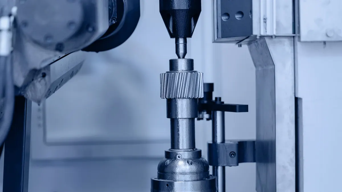
Home / Capabilities / Gear Manufacturing
Gear Manufacturing

Precision Gear Manufacturing From Blank to Final Inspection.

Gear shaping, hobbing and grinding are planned together with blank machining, heat treatment and gear inspection to match tooth geometry, material condition, accuracy requirements and production volume.

Internal & External GearsSpur & Helical GearsHard-Finished Gears

The manufacturing route and inspection plan are defined from the gear drawing, material, heat-treatment condition, quantity and required tooth accuracy.

Gear shaping, hobbing and grinding manufacturing processes
Three Core Gear Routes

Select the tooth-generation and finishing route around geometry, heat treatment and final accuracy.

Shaping and hobbing create the tooth form; grinding is introduced when hard finishing, tighter flank control or post-heat-treatment correction is required.

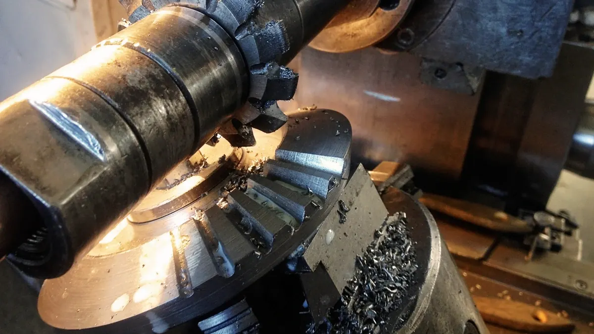
Gear Shaping

For internal gears, splines and tooth forms where cutter access or nearby shoulders limit other generating methods.

Gear Hobbing

A productive route for external spur and helical gears, pinions and repeat-production gear families.

Gear Grinding

Hard finishing for tighter tooth accuracy, flank geometry, surface quality and post-heat-treatment correction.

Gear shaping machining process
01 — Gear Shaping

Tooth generation for internal gears, splines and access-limited geometry.

Gear shaping is well suited to internal gears, external gears, splines and features positioned close to shoulders or inside recessed diameters. Process planning starts with cutter clearance, datum structure, blank condition, material and the required tooth accuracy.

Good fit for

  • Internal gears and internal splines
  • External spur and selected helical gears
  • Splines and tooth forms close to shoulders or recessed features

RFQ inputs

  • Module or DP, pressure angle and tooth count
  • Internal / external form, helix angle and face width
  • Material, hardness, datum scheme and quantity

Process strengths

Flexible cutter motion makes shaping useful for tooth forms that are difficult to access with a hob, especially internal geometry and shoulder-adjacent features.

Engineering considerations

Cutter and stroke clearance, workholding, blank runout, heat-treatment allowance and the final inspection method are reviewed before release.

Gear hobbing machining process
02 — Gear Hobbing

Productive tooth generation for external spur and helical gears.

Hobbing is typically preferred when the geometry allows continuous generating cutting of external teeth. It provides an efficient route for pinions, gear blanks and repeat-production families while maintaining consistent tooth geometry from part to part.

Good fit for

  • External spur gears
  • External helical gears
  • Pinions, gear shafts and repeat-production components

RFQ inputs

  • Module or DP, pressure angle, tooth count and helix data
  • Blank dimensions, bore / shaft datums and material condition
  • Lot size, annual demand and downstream heat treatment

Process strengths

Continuous generating action supports high productivity and repeatable tooth generation for many external gear families.

Engineering considerations

Hob approach and overrun, blank concentricity, datum runout, cutting allowance and any post-heat-treatment finishing are planned together.

Gear grinding finishing process
03 — Gear Grinding

Hard finishing for flank accuracy, profile and lead control.

Gear grinding is typically used after heat treatment to correct distortion and achieve the final tooth geometry and surface requirements. Generating or profile grinding routes are selected around gear geometry, accuracy targets, stock allowance and specified flank modifications.

Good fit for

  • Hard-finished spur and helical gears
  • Precision pinions and transmission components
  • Applications with tighter profile, lead, pitch or surface requirements

RFQ inputs

  • Required gear accuracy standard or drawing tolerances
  • Final hardness and heat-treatment route
  • Profile, lead, crowning or other flank modifications

Process strengths

Provides final tooth correction after heat treatment and supports tighter functional flank accuracy for demanding gear applications.

Engineering considerations

Grinding stock, heat-treatment distortion, datum relationships, flank modifications and required measurement reporting are defined before finishing.

Shaping, hobbing or grinding?

Use this comparison for early process planning. Final selection depends on tooth geometry, cutter access, material condition, heat treatment, target accuracy and production volume.

Decision factorGear ShapingGear HobbingGear Grinding
Primary roleTooth generation for internal / external gears and splines.Efficient external gear tooth generation.Final hard finishing and tooth-form correction.
Internal gearsStrong fit.Not normally used for internal teeth.Specialized and geometry-dependent.
External spur / helical gearsSuitable where geometry and cutter access favor shaping.Common production route.Common after heat treatment when tighter final accuracy is required.
Production profileFlexible from prototype through repeat production.Strong productivity for repeat batches and gear families.Added when final performance requires hard finishing.
Typical process positionTooth generation before final hard finishing where required.Usually tooth generation before heat treatment.Typically after heat treatment.
Key engineering questionCan the cutter and stroke clear the surrounding geometry?Does the blank and tooth geometry allow productive hob access?What final flank accuracy and correction are required after heat treatment?

Materials & Heat Treatment

Material and heat treatment are planned with the tooth-cutting and finishing route because hardness, distortion and stock allowance affect final gear accuracy.

  • Carbon and alloy gear steels
  • Stainless and specialty alloys where required by the application
  • Carburizing, nitriding, induction and through hardening by project requirement

Inspection & Gear Reports

Inspection is built around drawing datums, tooth geometry and the functional risk of the gear.

  • Bore / face datums, runout and concentricity
  • Tooth thickness, span or other functional tooth checks as specified
  • Profile, lead, pitch and gear-accuracy reports when required
  • Hardness, roughness and dimensional documentation

Complete Manufacturing Route

Gear production can be coordinated from machined blank through heat treatment, hard finishing and final inspection.

  • CNC turning and milling of blanks
  • Gear shaping or hobbing
  • Heat treatment and surface finishing
  • Gear grinding, inspection, marking and export packaging

Send your gear drawing for an engineering review.

Include gear type, module or DP, pressure angle, tooth count, helix angle, material, heat-treatment condition, accuracy requirement, quantity and inspection needs.

Upload CAD Package
MANAGED MANUFACTURING FOR CUSTOM MECHANICAL PARTS

Custom Mechanical Parts. One Engineering Interface.

CNC machining, molding, casting, forging and supporting processes matched to your drawing, material, tolerance, volume and quality requirements.

Engineering ReviewProcess MatchingQuality Control
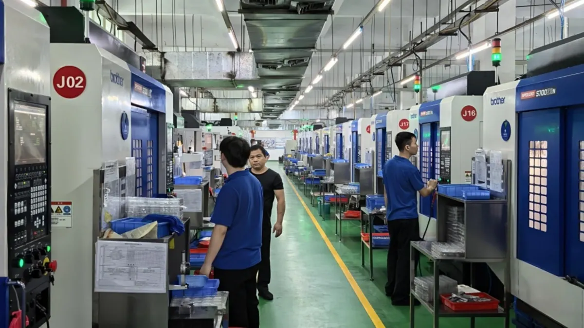
Home hero — CNC machining workshop
Drawing-led productionDrawing review → process planning → quality control → delivery
Manufacturing Capabilities

Multiple manufacturing processes. One project interface.

From CNC machining and molding to casting, forging, finishing and inspection, HSC coordinates the manufacturing route around the requirements of each part.

Home capability — CNC machining

CNC Machining

Multi-axis milling, precision turning, mill-turn, EDM and grinding for complex metal and plastic components.

Explore →
Home capability — casting and forging
Casting & Forging

Casting & Forging

Casting and forging routes selected around geometry, material, strength, volume and downstream machining requirements.

Explore casting & forging →
Home capability — quality assurance

Quality Assurance & Control

Inspection planning, CMM measurement, material documentation and quality reporting matched to drawing requirements.

Explore →
Home capability — value-added services

Value Added

Surface finishing, heat treatment, inserts, assembly, marking, kitting and packaging coordinated with primary production.

Explore →
How to Work With Us

From drawings to repeat production.

A clear project flow from initial files and engineering review through production and quality control.

01

Upload CAD

Share 3D CAD, 2D drawings and your material, quantity and quality requirements.

02

Engineering Review

We review manufacturability, process options, tolerances, materials and potential production risks.

03

Quote & Production Plan

Receive pricing, lead time, process recommendations and the proposed manufacturing route.

04

Production & Quality

Move from prototype or first article into repeat production with inspection and delivery coordination.

Industries

Manufacturing support for demanding industrial applications.

Experience across precision components for aerospace, automotive, robotics and other engineered products.

Case entryHome industry — Aerospace & Defense

Aerospace & Defense

Lightweight structures, precision interfaces and complex machined components.

Learn more →
Case entryHome industry — Automotive

Automotive

Prototype, tooling and production components for vehicle and mobility applications.

Learn more →
Case entryHome industry — Robotics

Robotics

Precision housings, brackets, shafts, gears and motion-system components.

Learn more →
Selected Manufacturing Examples

Representative precision components.

Home case example — precision machined housing

Precision Machined Housing

Complex cavities, precision bores, controlled datums and multi-face machining for functional assemblies.

View machining routes →
Home case example — precision structural bracket

Precision Structural Bracket

Lightweight structures with controlled mounting interfaces, critical features and inspection requirements.

View precision manufacturing →
Materials We Work With

Materials selected around function, process and production requirements.

Commonly supported metals, engineering plastics and elastomers cover applications from precision machining to molding, casting and forging.

Metals

Aluminum, stainless steel, carbon and alloy steels, brass, copper and titanium.

Open metals guide →

Plastics & Elastomers

ABS, PC, POM, Nylon, PMMA, PP, PE, TPU, TPE and silicone for machined and molded components.

Use comparison filter →
Why Work With Us

One project team across multiple manufacturing routes.

Hangzhou Sino-Turk Supply Chain (HSC), the supply-chain company within SINO-TURK Innovation (STI), manages sourcing, engineering coordination, quality follow-up and delivery across qualified manufacturing resources.

Engineering supportDFM, process selection, material review and tolerance planning.
Flexible ManufacturingCNC, molding, casting, forging and supporting processes through one project interface.
Prototype to productionSupport from initial samples and first articles through repeat production.
International Project SupportEnglish communication, documentation coordination and export delivery support.
Knowledge Center

Practical resources for better manufacturing decisions.

Use our guides to prepare RFQs, compare processes, select materials and define inspection requirements.

Guide

Design for Manufacturability Basics

Checklist for wall thickness, corner radii, undercuts and tolerances.

Read guide →
Video

CNC Machining Planning

A practical overview of milling, turning, EDM and inspection planning.

Watch →
Documents

Request Current Capability Documents

Request the current capability summary and relevant qualification documents from our team.

Request documents →

Ready to quote your mechanical parts?

Share your CAD files, drawings, material, quantity, tolerance, finish and inspection requirements. Our team will review the project and recommend a suitable manufacturing route.

Start Your RFQ
Home / Industries
Industry Experience

Engineering Case Studies Across Demanding Industries

Three manufacturing case studies showing how HSC coordinates specialized production resources, process controls and quality evidence for different engineering requirements.

Manufacturing case studies across aerospace, automotive and robotics
Explore case studies
Selected Case Studies

Different industries require different manufacturing control strategies.

These three projects show how one HSC project interface can coordinate different materials, manufacturing routes, quality frameworks and production priorities through qualified production resources.

Aerospace titanium and composite case
01

Aerospace & Defense

Flight-critical titanium fitting on a composite airframe interface.

  • Ti-6Al-4V + CFRP
  • GD&T and hybrid stack holes
  • AS9102 FAI and traceability
Enter case study →
Automotive gear manufacturing case
02

Automotive

High-volume helical gear for transmission and EV reducer applications.

  • 15,000–25,000 pcs / month
  • Heat-treatment distortion control
  • PPAP and SPC logic
Enter case study →
Robotics actuator case
03

Robotics

Precision rotary actuator components for robot joint systems.

  • System-level backlash control
  • Datum-chain management
  • CMM and runout validation
Enter case study →
Case Study 01 / Aerospace & Defense

Flight-Critical Titanium Fitting on Composite Airframe Interface

HSC coordinated the manufacturing program for a load-bearing hinge fitting that transfers actuator load into a composite airframe structure. The project combined titanium machining, CFRP interface control, hybrid stack holes and aerospace documentation requirements.

TitaniumCFRP Composite5-Axis CNCAS9102 FAI
Aerospace case image
Industry Segment
Aerospace & DefenseFlight-control / airframe interface hardware
Part Function
Load-bearing hinge fittingTransfers actuator load into composite airframe structure
Material System
Ti-6Al-4V + CFRPAMS 4928 titanium, interface skins and hybrid fastener stacks
Production Volume
12 pcs FAI+ 180 pcs low-rate production
Lead Time
10 / 25 working daysFAI lot / production after approval
Quality Framework
AS9100-alignedAS9102 FAI, serialization and lot integrity

Engineering Challenges

The challenge is not only machining a titanium part, but keeping geometry, laminate condition, hole quality, surface integrity and traceability controlled together.

01

Flight-Safety Dimensional & Geometric Control

Multiple datum-referenced GD&T callouts had to remain aligned across a flight-critical interface.

  • GD&T-driven datum strategy
  • True position and profile control
  • Hole-to-hole location consistency
02

Titanium Machining Stability

Deep pockets, thin load-path walls and fatigue-sensitive radii created distortion risk.

  • Deep pockets and thin walls
  • Residual stress after unclamping
  • Fatigue risk if distortion is uncontrolled
03

Composite Machining Protection

CFRP interface machining required laminate-safe processing instead of ordinary metal-drilling practice.

  • Delamination prevention
  • Fiber pull-out avoidance
  • Resin burn control
04

Hybrid Material Interface

Titanium + CFRP stack holes had to remain accurate while protecting composite exit condition.

  • Titanium + CFRP stack holes
  • Countersink control
  • Exit breakout risk management
05

Bonding Surface Integrity

Bond and seal surfaces needed controlled roughness and undamaged edges.

  • Surface condition control
  • Edge integrity
  • No contamination or torn fibers
06

FOD & Traceability

Every part needed dimensional evidence and documentation integrity.

  • Serial identity
  • Heat-lot linkage
  • Inspection evidence

Coordinated Manufacturing Strategy

Process separation, geometry stability and FAI-ready evidence.
01
Material Verification

Titanium mill certs and composite batch identity confirmed before release.

02
DFM Review

Datum scheme, fillets, hole stack sequence and tool access reviewed.

03
5-Axis CNC Machining

Rigid fixturing and in-process probing controlled titanium geometry.

04
Stress Relief Control

Stability checks after roughing and post-stress-relief operations.

05
Composite Trim / Drill

Dedicated composite tooling, dust extraction and backup support.

06
Inspection

Geometry verification, laminate checks and FAI documentation.

HSC Project Coordination

HSC coordinated titanium machining, composite processing and inspection around one project control plan. Material-specific operations were separated to reduce cross-contamination and FOD risk while datum, tooling and FAI requirements remained aligned.

  • Rigid fixturing plus in-process probing
  • Dedicated composite trim/drill setup
  • Controlled drill and countersink sequence
  • DFM around datum definition and tool access
  • Inspection evidence prepared for AS9102 FAI

Quality & Release Controls

Mill Certificate VerificationIncoming titanium material identity and certification check.
Composite Batch IdentificationCFRP batch traceability and interface processing control.
In-Process InspectionChecks after roughing, stress relief and composite trim/drill.
100% CMMFull dimensional verification against GD&T requirements.
Laminate ReviewDelamination, breakout, countersink and edge checks.
AS9102 FAIFirst-article package with serialized traceability.

Result

FAI accepted on first submission.

Production parts met positional and profile requirements without dimensional rejection. Composite holes and trim edges passed laminate criteria, and each shipment included complete traceability documentation.

GeometryPosition and profile requirements achieved.
Composite IntegrityNo delamination findings.
DocumentationTraceability pack released with shipment.
Case Study 02 / Automotive

High-Volume Helical Gear for Automotive Transmission / EV Reducer

This program shows how high-volume gear production was coordinated around stable series accuracy, heat-treatment distortion control, NVH performance and PPAP discipline — not simply one successful sample.

Helical GearHeat TreatmentGrindingPPAP
Automotive case image
Industry Segment
AutomotiveICE transmission and e-mobility reducer gears
Part Function
Helical gearTorque transmission in compact gearbox systems
Material System
Case-hardening steel20CrMnTi / 20MnCr5 / 8620 with heat-lot certification
Production Volume
500 pcs validation15,000–25,000 pcs / month
Lead Time
18 working daysValidation lot; weekly call-off after process approval
Quality Framework
IATF 16949-alignedPPAP, control plan and SPC on critical gear features

Engineering Challenges

Automotive gears are judged by production stability. The program required tooth geometry, heat-treatment movement, metallurgy, inspection and launch documentation to remain controlled as one manufacturing system.

01

Gear Accuracy Stability

Series output had to maintain the agreed gear accuracy grade over large quantities.

  • Profile consistency
  • Lead and pitch stability
  • Runout control in production
02

Heat-Treatment Distortion

Tooth geometry movement after carburizing and hardening had to be anticipated before grinding.

  • Distortion compensation
  • Pre-grind stock planning
  • Stable finish cleanup
03

NVH Optimization

Contact pattern and surface condition directly affected gear whine.

  • Contact pattern control
  • Crowning and relief optimization
  • Surface quality after grinding
04

Case Depth & Hardness

Metallurgical quality was as critical as tooth geometry.

  • Case depth window
  • Core hardness verification
  • Wear-life protection
05

Grind Burn Control

Surface integrity needed protection against burn, tensile stress and early pitting.

  • Burn screening
  • Grinding parameter control
  • Critical flank monitoring
06

PPAP / Change Management

Launch documentation and post-SOP change control had to remain locked.

  • PPAP pack readiness
  • Control plan integrity
  • Fixture / recipe change control

Coordinated Manufacturing Strategy

Route planned to absorb heat-treatment movement and stabilize series capability.
01
Turning

Base geometry and controlled references prepared.

02
Hobbing

Tooth geometry generated with pre-planned stock.

03
Chamfer & Deburr

Assembly surfaces and edge condition controlled.

04
Carburizing & Hardening

Metallurgical process window applied.

05
Grinding

Profile, lead and surface characteristics finished.

06
Gear Measurement

Gear charts, contact pattern and hardness verified.

HSC Project Coordination

HSC aligned the gear manufacturing partner, heat-treatment route, grinding stock and inspection plan so heat-treatment movement was treated as a planned process input rather than a downstream defect.

  • Crowning, relief and grind stock refined
  • Contact-pattern review for NVH support
  • Metallurgical checks linked to release criteria
  • Deburr and chamfer controlled as process characteristics
  • PPAP and change-control expectations locked into program plan

Quality & Release Controls

Gear Measuring CenterProfile, lead, pitch and runout verification.
Heat-Lot VerificationIncoming steel and heat-lot confirmation.
In-Process ChecksInspection after hobbing and heat treatment.
Contact Pattern ReviewValidation checks for meshing and NVH behavior.
Case Depth & HardnessWear-life and strength window verification.
PPAP PackageLaunch documentation and SPC sampling logic.

Result

Validation lot approved for SOP.

Series gears held the agreed accuracy grade with stable contact pattern. NVH performance remained within specification, and the shortened grind cycle improved cost efficiency.

Series StabilityAccuracy grade held in repeat production.
FunctionContact pattern and NVH stayed within target.
LaunchPPAP and process control supported SOP.
Case Study 03 / Robotics

Precision Rotary Actuator Components for Robot Joint

In robotic actuation, low backlash and repeatable motion are determined by the full mechanical stack — not by one isolated part tolerance.

Low BacklashDatum ChainThin-Wall HousingCMM Validation
Robotics case image
Industry Segment
RoboticsCompact joint / rotary actuator hardware
Part Function
Housing, flange, rotating stackCarry motor torque to robot arm with low backlash
Material System
Aluminum + alloy steelHousing and output flange; internal gear / cam elements and shaft
Production Volume
20 prototype sets+ 400–800 sets low-rate production
Lead Time
12 / 22 working daysPrototype / production after dimensional freeze
Quality Framework
Incoming-to-final inspectionCMM on datum stack, gear and runout reports

Engineering Challenges

The true challenge is whether bores, bearing seats, gear axes and mounting faces remain controlled as one motion system.

01

Backlash Is a System-Level Specification

The actuator is judged by lost motion at the output, not by whether each part is individually in tolerance.

  • Housing bore
  • Bearing seats
  • Gear axis
  • Output flange register
02

Thin-Wall Structure Control

Lightweight housing geometry created deformation risk affecting motion quality.

  • Bore roundness
  • Flange flatness
  • Encoder accuracy risk
03

Datum Chain Management

Motor, bearing, gear center and encoder faces needed one controlled datum logic.

  • Motor pilot alignment
  • Bearing bore relationship
  • Gear center consistency
  • Encoder mounting accuracy
04

Precision Internal Components

Planetary, cycloidal or wave-generator elements depend on precise profile and position.

  • Gear profile
  • Pin-hole position
  • Thickness control
05

Bearing & Seal Interface

Assembly-ready surfaces were essential for preload, sealing and cleanliness.

  • Preload-sensitive seat geometry
  • Leakage path control
  • Burr management
06

Production Repeatability

Actuator performance had to remain interchangeable from lot to lot.

  • Stable fixtures
  • Runout repeatability
  • Inspection consistency
Engineering InsightBacklash is not a single-part tolerance issue. In a robot joint, it is a system-level accuracy problem driven by the complete mechanical stack.

Coordinated Manufacturing Strategy

One datum strategy across the structure, rotating components and validation stack.
01
5-Axis Machining

Housing and output flange features finished from controlled datums.

02
Precision Turning

Shaft and rotating interfaces produced with controlled geometry.

03
Gear Component Processing

Profile, position and thickness held on internal elements.

04
Controlled Deburring

Bearing and seal seats protected from burrs and chips.

05
Stack Validation

Critical rotating stack match-checked before release.

06
Final Inspection

Bore position, runout, stack concentricity and assembly readiness verified.

HSC Project Coordination

HSC coordinated housing, shaft and gear-component production around one datum and validation strategy. The actuator envelope and load path remained unchanged while bearing-seat access, fillet stiffness and datum definition were optimized for stable manufacture and repeat orders.

  • One datum strategy from motor interface to output flange
  • Gear stock and pin-hole positions set for assembly contact
  • Bearing and seal seats released after controlled deburr
  • Validation assembly confirmed system-level performance
  • Same fixture and inspection pack retained for repeat orders

Quality & Release Controls

Datum InspectionHousing datums, flange face and feature relationships.
CMMBore position, datum stack and hollow-shaft runout.
Bore MeasurementIn-process checks after roughing and finishing.
Runout VerificationRotating surfaces and output-flange accuracy.
Gear InspectionInternal gear / cam profile, position and thickness.
Assembly ValidationStack concentricity, backlash window and cleanliness.

Result

Required backlash and runout performance achieved.

Production lots maintained flange and bore concentricity without rework. No seal-seat or chip-related assembly rejects were reported, and repeat orders used the same fixture and inspection baseline.

Motion AccuracyBacklash and runout stayed within the agreed window.
AssemblyNo seal-seat or chip-related assembly rejects.
RepeatabilitySame fixture and inspection pack reused.

One project interface. The right manufacturing route for your industry.

Share drawings, material requirements, quality expectations and production targets. HSC will review the project, match suitable manufacturing resources within the STI network, and coordinate quality and delivery through one project interface.

Home / Work With Us
Work With Us

Start your manufacturing project with one engineering interface.

Share CAD files, drawings or early-stage requirements. HSC coordinates engineering review, process selection, quotation, production, quality and delivery across STI Group manufacturing resources and qualified partners.

Engineering review for a custom manufacturing project
Start With Your Drawings

Share your files for engineering review.

When CAD files, 2D drawings or reference photos are available, HSC reviews geometry, material, tolerance, volume and process risks before quotation.

Accepted file typesSTEP, STP, IGS, IGES, DXF, DWG, PDF, ZIP and RAR can be included with your RFQ.
What to includeMaterial, quantity, tolerance, finish, critical dimensions and application details help us review the project faster.
Confidential projectsRequest NDA review before sharing complete technical packages when the design or application is sensitive.
Molding-specific RFQsInclude resin or performance requirements, annual volume, target tool life, cavities, cosmetic zones, inserts and validation needs.
Request a Manufacturing Quote

Turn your requirements into a clear manufacturing plan and quote.

For prototypes, bridge production and repeat orders, HSC reviews the project and confirms the proposed process route, commercial assumptions and quality scope.

01

Submit RFQ

Share drawings, quantity, material, tolerance, finish and application requirements.

02

Engineering & DFM Review

We review manufacturability, critical features, process options and potential production risks.

03

Manufacturing Route & Quote

Receive pricing, lead time and the proposed production, inspection and documentation approach.

04

Sample to Production

Move from prototype or first article into repeat production with quality and delivery coordination.

Direct Engineering Support

Not ready to upload? Talk to an engineer first.

Use this route when the manufacturing process is unclear, tolerances are critical, the project combines multiple processes, or you want to discuss confidentiality before sharing complete files.

Process selectionDiscuss CNC, molding, casting, forging or supporting processes before the RFQ is finalized.
DFM & tolerancesReview critical dimensions, datum strategy, manufacturability and inspection expectations.
Multi-process projectsCoordinate parts that require primary manufacturing, finishing, assembly or multiple specialized resources.
Confidentiality & NDADiscuss NDA requirements and the safest way to share sensitive drawings or development files.

1RFQ Type

2Part Quote Information

3Upload Technical Package (Optional)

4Contact Information

Complex or Confidential Project?

Start with a technical discussion before sending the full package.

We can review process direction, critical requirements and confidentiality needs first, then confirm the best way to proceed with your RFQ.

Home / Materials
Material Selection & Manufacturing Fit

The right material starts with the application — and ends with a controlled production route.

HSC helps translate mechanical, environmental, cosmetic and compliance requirements into a practical material-and-process route, then coordinates the selected manufacturing partner around the approved grade, documentation and quality requirements.

Metals, engineering plastics, elastomers and composite materials
Material FamiliesSelection CriteriaCompareProcess FitGrade & DocumentationApplications
Material Families

Four material families. Different routes, trade-offs and qualification needs.

The list below is a practical starting point for RFQ planning. Exact grade, temper, reinforcement, form and source are confirmed against the drawing and selected production route.

Lightweight structures

Composites

CFRP, GFRP, epoxy-based laminates, thermoplastic composites and hybrid structures for applications where stiffness-to-weight, corrosion resistance or tailored performance matters.

  • CFRP / GFRP structures
  • Layup, molding and secondary machining
  • Fiber orientation and laminate design matter
Compare composites →
Structural & precision

Metals

Aluminum, stainless steel, carbon/alloy steel, brass, copper and titanium across CNC machining, EDM, casting, forging and related secondary processes.

  • Strength, fatigue and wear requirements
  • Heat treatment and surface finish options
  • Grade, temper and mill certification control
Compare metals →
Functional & molded

Engineering Plastics

ABS, PC, POM/acetal, PA/Nylon, PBT, PMMA, PP, PE and selected high-performance polymers for machined, molded and assembled components.

  • Impact, wear and dimensional stability
  • Reinforced and flame-rated grades
  • Moisture, color and resin-lot control
Compare plastics →
Flexible & sealing

Elastomers / Rubber

Silicone / LSR and TPU / TPE options for flexible, sealing, soft-touch, impact-absorbing and wear-resistant components, subject to exact grade and process review.

  • Hardness and compression behavior
  • Temperature and chemical exposure
  • Overmolding / compatibility review
Compare elastomers →
Selection Criteria

Material choice is more than strength and price.

HSC reviews material selection together with geometry, process capability and end-use conditions so the proposed route is technically and commercially realistic.

01

Mechanical duty

Static load, fatigue, impact, wear, stiffness, friction and required safety margin.

02

Operating environment

Temperature, chemicals, corrosion, UV, moisture, electrical or thermal requirements.

03

Manufacturing route

Machinability, moldability, castability, forgeability, stock form, wall section and production volume.

04

Quality & compliance

Exact grade, certificate scope, traceability, special-process records and customer-specific requirements.

Material Comparison

Filter by material family and engineering priority.

Use these cards for early route selection only. Final material suitability depends on the exact grade, condition, geometry, process and service environment.

Aluminum

Lightweight, machinable and widely used for housings, brackets, plates and structural components.

Low weightCNC friendlyAnodizing options
Typical examples: 6061, 6082, 7075 and other project-specified grades/conditions.

Stainless Steel

Corrosion-resistant material family for precision mechanical, structural and harsh-environment components.

Corrosion resistanceStrengthCleanability
Typical examples: 303, 304/304L, 316/316L, 17-4PH subject to requirement.

Carbon & Alloy Steel

Broad strength, toughness and heat-treatment options for shafts, gears, tooling and load-bearing parts.

High loadHeat treatableWear resistance
Typical examples: low/medium-carbon and alloy steels selected to drawing or customer standard.

Brass

Good machinability and corrosion behavior for fittings, bushings, connectors and precision turned parts.

MachinableConductiveCorrosion resistant
Grade control: alloy and lead-content requirements are confirmed before sourcing.

Copper

Selected where electrical or thermal conductivity is important, including terminals and heat-transfer components.

ElectricalThermalSpecial handling
Grade control: conductivity, temper and alloy are specified by project.

Titanium

High strength-to-weight and corrosion resistance for demanding structural and precision applications.

High specific strengthCorrosion resistantProcess sensitive
Typical examples: commercially pure grades and Ti-6Al-4V where specified.

ABS

General engineering plastic for housings, prototypes and molded components where balanced cost and appearance matter.

HousingPrototypeMolding
Grade control: color, impact grade, flame rating and recycled content are project-specific.

PC

Impact-resistant engineering plastic used for covers, housings and functional components, including transparent grades.

ImpactTransparency optionsMolding
Grade control: optical, UV, flame and compliance requirements are confirmed by exact resin grade.

POM / Acetal

Low-friction, dimensionally stable engineering plastic for gears, bushings, guides and sliding mechanical parts.

Low frictionStableMachinable
Grade control: homopolymer/copolymer and brand-specific material are confirmed when required.

PA / Nylon

Tough, wear-resistant family for gears, rollers, structural molded parts and reinforced mechanical components.

WearToughnessFilled grades
Grade control: PA6/PA66, reinforcement and moisture conditioning affect final performance.

PMMA / Acrylic

Clear material for windows, guards, light guides and parts where optical appearance is more important than high impact strength.

OpticalMachinableAppearance
Grade control: optical quality, UV exposure and surface-finish expectations are defined by project.

PP / PE

Lightweight, chemically resistant families for covers, containers and functional components with moderate structural demands.

Chemical resistanceLow densityMolding
Grade control: exact polymer family, filler and application requirements must be specified.

High-Performance Polymers

Selected engineering grades can support higher temperature, chemical or wear requirements where standard plastics are insufficient.

High temperatureChemicalProject specific
Examples: PEEK, PPS and other grades only when confirmed for the selected project and production route.

Silicone / LSR

Flexible material family for seals, gaskets, soft-touch components and selected temperature-sensitive applications.

FlexibleTemperatureSealing
Grade control: hardness, cure system, color and compliance requirements are confirmed by exact material.

TPU / TPE

Flexible thermoplastic options for protective parts, grips, overmolded interfaces and wear-resistant components.

WearSoft touchOvermolding
Grade control: hardness, bonding compatibility and process window are validated with the molding route.

CFRP

Carbon-fiber reinforced structures for high stiffness-to-weight applications, with laminate architecture defined around load direction and geometry.

Very lightweightHigh stiffnessAnisotropic
Project variables: fiber type, resin system, layup, cure route and machining/edge requirements.

GFRP

Glass-fiber reinforced structures for corrosion resistance, electrical insulation and cost-sensitive composite applications.

InsulatingCorrosion resistantStructural
Project variables: resin system, fiber content, laminate form and finish requirements.

Engineered / Hybrid Composites

Epoxy laminates, thermoplastic composites and hybrid reinforcement systems selected when a tailored property balance is required.

Tailored propertiesThermal optionsProject specific
Qualification: material system and production method are confirmed together; generic family names are not treated as interchangeable grades.
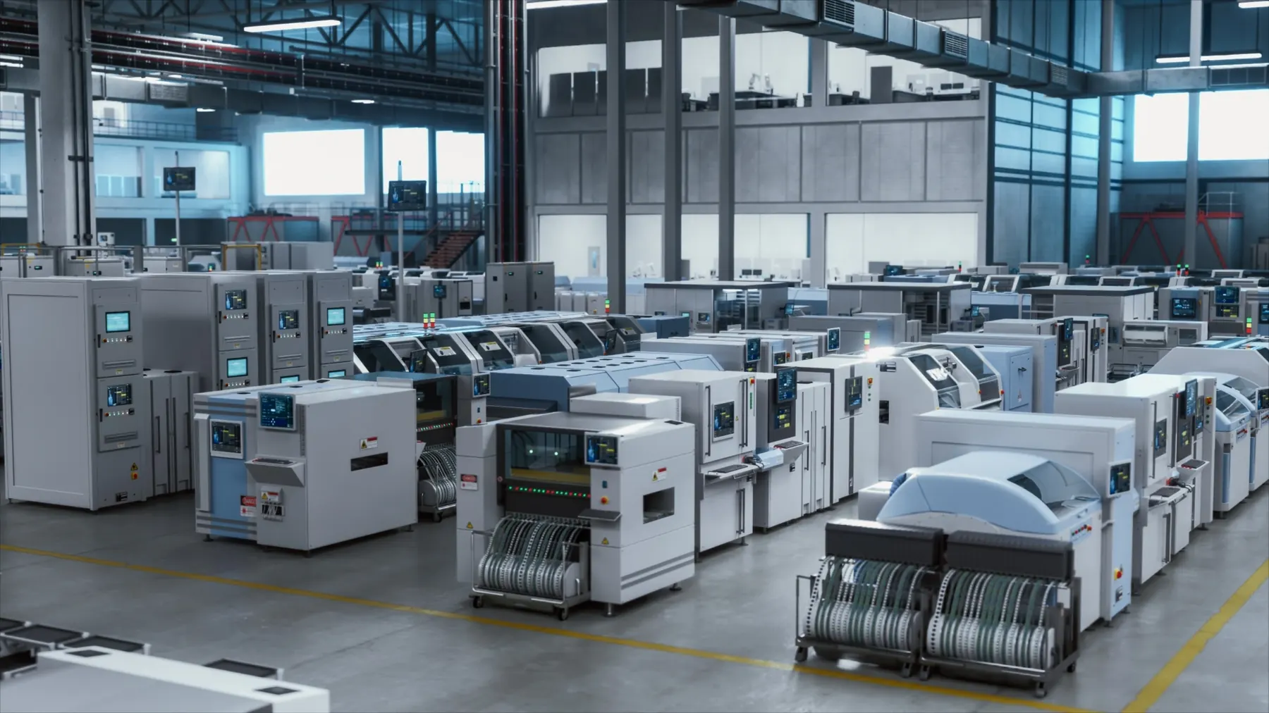
Comparison note: These are qualitative planning cues, not engineering allowables. Mechanical properties, temperature limits, corrosion behavior and processing response can vary significantly by grade, temper, reinforcement, supplier and manufacturing condition.
Material × Process Fit

The same material family can require a very different production route.

HSC matches material, geometry, tolerance, volume and documentation needs before confirming the manufacturing partner and process plan.

RouteTypical Material FamiliesWhat is confirmed for the RFQ
CNC machiningAluminum, steels, stainless steel, brass, copper, titanium and machinable engineering plasticsExact grade/condition, stock form, machining strategy, tolerance, finish and inspection scope.
EDM / grindingConductive steels, stainless, copper alloys and tool materialsMaterial condition, hardness, recast/finish requirements, datum strategy and reporting.
RouteTypical Material FamiliesWhat is confirmed for the RFQ
Injection moldingABS, PC, PP, PA/Nylon, POM, PBT and selected engineering resinsExact resin grade, filler, color, flame/UV requirements, moisture control, recycled content and annual volume.
Overmolding / flexible moldingTPU, TPE and compatible rigid-substrate systemsBonding compatibility, hardness, insert/substrate material and trial/validation plan.
Silicone / LSRProject-specified silicone systemsHardness, cure system, application requirements, production-site capability and required documentation.
RouteTypical Material FamiliesWhat is confirmed for the RFQ
Die castingAluminum and zinc casting alloysAlloy, pressure-casting route, wall section, tooling, porosity/cosmetic requirements and secondary machining.
Vacuum / urethane castingPU-like casting resins and silicone tooling systemsTarget appearance/property, master pattern, quantity, color and prototype-use expectations.
ForgingCarbon/alloy steel, stainless, aluminum and selected alloysGrade, forging condition, heat treatment, machining allowance, grain-flow/load requirements and testing.
RouteTypical Material FamiliesWhat is confirmed for the RFQ
Composite fabricationCFRP, GFRP, epoxy laminates and selected thermoplastic/hybrid systemsLaminate architecture, fiber/resin system, cure route, tooling, inserts, trim/machining and inspection plan.
Composite machining / finishingCured composite structures and laminatesEdge quality, delamination control, dust/extraction requirements, hole tolerance and protection of finished surfaces.
Grade, Source & Documentation

Material identity stays tied to the project — not just the family name.

HSC coordinates material requirements with the selected production partner and consolidates the agreed documentation into the project quality package.

Material Control

Exact grade first. Substitution only by approval.

Where a drawing, customer specification or industry requirement defines a material grade, condition, standard or approved source, that requirement is carried into the manufacturing plan. Proposed equivalents or substitutions are not treated as automatic replacements and should be approved before production.

Grade & condition confirmationAlloy/resin designation, temper or heat-treatment condition, reinforcement, hardness and stock form are checked against the RFQ.
Material certificatesMTC/MTR, COA, resin-lot records or other agreed evidence can be included where required and available for the selected source.
Lot / heat traceabilityHeat numbers, lot identity and part-level or batch-level traceability are coordinated when specified by the project.
Compliance by exact grade & siteUL, FDA food-contact, RoHS, REACH, Prop 65 and controlled-environment requirements are verified against the exact material grade and intended production site when applicable.
Availability note: Material availability, minimum order quantity, mill/resin source, certificate scope and lead time vary by grade, form, quantity and production route. These are confirmed during quotation rather than assumed from the generic material family.
Application View

Material choices aligned with the three industry programs currently shown on our site.

These examples illustrate common starting points. The final material is always confirmed against the actual drawing, load case, environment and production route.

A&D

Aerospace & Defense

Titanium, high-strength aluminum, stainless/alloy steels and CFRP can support lightweight structural and precision applications where material identity, traceability and process control are critical.

AUTO

Automotive

Aluminum, steels, engineering plastics and elastomers are matched to load, wear, cost, cycle volume, heat treatment, surface treatment and assembly requirements.

ROBO

Robotics

Aluminum, stainless/alloy steels, POM/PA and CFRP are common starting points for housings, shafts, gears, joints and lightweight moving structures.

Have a drawing but not a final material route?

Send the CAD, drawing, quantity and working environment. HSC can review the requirements, compare practical material/process options and coordinate the selected production route through quotation and release.

Upload Project Files
Home / Capabilities / Molding & Tooling
Molding & Tooling

Injection Molding & Tooling

DFM, mold design, tool build, injection molding and post-mold operations coordinated around resin, geometry, annual volume and quality requirements.

DFM & tooling integration128–260T molding rangeEngineering thermoplasticsTrial & quality documentation

From first DFM review through T0/T1/T2 validation and repeat production, one project team keeps tooling, process and inspection aligned.

Injection molding page hero
From tool design to productionDFM, tooling, trials, molding and quality control
Explore this page
Service Overview

Build the tool and molding process around the part.

Molding projects are planned from geometry, resin, annual volume, cosmetic requirements, assembly needs and validation scope—not from press tonnage alone.

Project Approach

One engineering path from DFM to stable production.

HSC coordinates DFM, mold design, filling and warpage analysis when needed, tool construction, trials, process validation, inspection and post-mold operations through one project interface.

DFM before steel

Review wall thickness, draft, ribs, bosses, undercuts, gate, parting line and ejection risk before tool release.

Tooling matched to volume

Select steel, cavitation, runner, cooling and texture around expected production volume, resin and service-life requirements.

Production validation

Use structured trials, approved samples, process parameters and dimensional or cosmetic criteria before repeat production.

128–260Tcurrent molding range
DFM-ledtooling decisions before build
Multi-cavityrepeat-production options
T0–T2structured trial & validation
01

Production Injection Molding

Production molding for engineering thermoplastics, structural components and cosmetic parts.

  • 128–260T molding range for suitable projects
  • Press selection based on projected area, shot weight and mold envelope
  • Single- or multi-cavity tooling selected around volume and cycle requirements
02

Insert & Overmolding

Combine molded substrates, soft-touch materials or installed metal hardware.

  • Plastic-over-plastic and soft-touch applications
  • Metal inserts, threaded hardware and retained components
  • Substrate compatibility, bond, temperature and dimensional effects reviewed during DFM
03

Complex Molding Programs

Higher-complexity parts that require closer coordination between tooling, material and process.

  • Thin-wall, ribbed and precision-interface features
  • Filled and engineering-resin applications
  • Automation or controlled-environment requirements reviewed where the project requires them
04

Post-Mold Operations

Complete molded parts with machining, joining, marking, hardware and assembly.

  • Secondary CNC, trimming and deburring
  • Printing, laser marking, heat staking and ultrasonic welding
  • Functional checks, kitting and customer-specific packaging
Tooling Capability

Tooling planned for part quality, cycle stability and service life.

Mold design and build decisions are tied to resin, geometry, annual volume, cosmetic requirements and maintenance expectations.

DFM

Design Review

  • Part geometry, draft, wall thickness, ribs, bosses and undercuts
  • Gate, parting line and ejection review
  • Filling, cooling and warpage analysis when useful
BUILD

Tool Construction

  • Prototype, bridge and production tooling
  • Cold-runner and hot-runner options
  • Single-cavity, multi-cavity and family tools where appropriate
STEEL

Common Tool Steels

  • 718H
  • H13
  • S136
  • Steel selection matched to resin, fillers, surface requirement and expected tool life
LIFE

Maintenance & Tool Life

  • Tool-life target based on steel, resin, fillers, geometry and cavitation
  • Preventive-maintenance plan aligned with production volume
  • Protected storage and maintenance records for repeat programs
Tooling planning: Expected tool life is defined per project based on tool steel, resin and fillers, part geometry, cavitation, process conditions and maintenance. Tool ownership, storage and maintenance arrangements are documented with the quotation.
Production Planning

Start with the part—not a generic press limit.

Press selection is based on projected area, shot weight, mold envelope, resin, process window and required automation. The values below support early RFQ planning.

Current supported molding range is 128–260T. Final equipment and tooling details are selected after DFM.
Planning itemCurrent guideEngineering check
Press range128–260TClamp force, tie-bar and platen limits, mold height and process margin.
Part & mold envelopePart-specificMold dimensions, ejection, cooling connections and automation clearance.
Shot capacityPress- and resin-specificPart plus runner weight, resin density, screw size and process cushion.
CavitationSingle or multi-cavity by programAnnual volume, cycle balance, tool complexity, quality risk and service-life target.
Process controlProject-specificMold temperature, critical parameters, sensors and validation requirements.
Tooling lead timeProject-specificPart complexity, steel, cavitation, runner system, texture and trial plan.
Molding Materials

Engineering resins selected for function, molding behavior and compliance.

Resin family alone is not enough. Grade, reinforcement, flame rating, color, moisture control, recycled content and documentation are reviewed against the application.

Common thermoplastics

ABSPCPPPA / NylonPOM / AcetalPBT

Engineering & flexible options

TPU / TPEGlass- or mineral-filled gradesFlame-retardant / UV-stabilized gradesCustomer-specified resins
Material compliance: UL, FDA food-contact, RoHS, REACH and Prop 65 requirements are reviewed against the exact resin grade and intended production site. Recycled content is used only when specified or approved. Controlled-environment requirements are confirmed as part of project planning.
Molding Quality Control

Validate the mold, process and finished part before repeat production.

Dimensional, cosmetic, material and process requirements are defined before trials so T0/T1/T2 decisions are based on agreed acceptance criteria.

Molding control plan

From trial samples to stable repeat production.

Trial reports, approved samples, process parameters, in-process checks, final inspection and material traceability can be combined into the project control plan.

DFMT0/T1/T2Approved SampleProduction Release
Dimensional reportsFull-dimensional, CMM or feature-specific reports can be supplied to the agreed inspection scope.
Cosmetic standardsDefine visible zones, texture, color and defect criteria against approved samples or customer standards.
Process recordsApproved molding window, critical settings and process-change control can be retained for repeat production.
Capability studiesCp/Cpk or other capability studies can be planned for specified critical characteristics when required.
Material traceabilityResin grade, lot identity, COA and color-master records can be included where required.
Corrective actionNonconformance segregation, root-cause review and 8D response can be included by project.
Quality-system requirements: Where a project requires ISO 9001 or ISO 13485 scope, applicability is verified against the selected production site before order release.
Post-Mold Operations

Take molded parts beyond the press.

Secondary machining, joining, marking, hardware installation, inspection and packaging can be integrated into the same project plan.

CNC

Secondary machining

Machine critical holes, faces, threads and interfaces after molding.

Trimming & finishing

Deburring, polishing, blasting, painting and selected surface treatments.

US

Plastic joining

Heat staking, heat riveting and ultrasonic welding for compatible part designs.

Marking & decoration

Pad printing, silk screen, laser marking, labels and customer-specified identification.

Hardware & assembly

Thread inserts, press-fit hardware, subassembly and functional checks.

Inspection & kitting

Final sorting, labeling, customer packaging, kits and release documentation.

Molding Workflow

From CAD to validated molding production.

DFM, tooling, trials and production release are managed as linked engineering stages.

01

DFM & project definition

Review 3D/2D files, resin, annual volume, cosmetic zones, tolerances, inserts and documentation needs; identify tooling and molding risks.

02

Tool design & build

Define steel, cavitation, gating, runner, cooling, ejection, texture and the mold-trial plan.

03

Trial & validation

Review T0/T1/T2 samples for dimensions, appearance and process behavior; complete corrections and approve the production sample.

04

Production & control

Run released parameters, maintain material-lot traceability, perform in-process and final inspection, and supply agreed documentation.

Typical Applications

Molded components for industrial and engineered products.

Application fit is determined by resin, geometry, cosmetic needs, validation scope and any required quality-system or compliance documentation.

Aerospace & specialized equipment

Lightweight covers, clips and equipment components subject to project-specific material, qualification and documentation requirements.

Medical equipment

Device housings and instrument-related plastic parts where the selected resin and production-site quality system fit the project.

Automotive & mobility

Functional housings, clips, brackets, inserts and repeat-production components.

Industrial automation

Protective covers, control components, fixtures and engineered plastic parts for equipment and machinery.

Electronics & semiconductor equipment

Insulating parts, equipment components, fixtures and assembled plastic/metal interfaces.

Multi-material & insert components

Overmolded interfaces, threaded inserts, retained hardware and higher-complexity engineered-plastic parts.

Molding FAQ

Questions to resolve before tooling release.

Clear inputs on resin, annual volume, critical features, cosmetic requirements and validation needs help us choose the right tooling and production route.

Yes. A 3D model is enough for an initial review, but a 2D drawing is strongly recommended for tolerances, threads, inserts, texture, cosmetic zones, assembly interfaces and inspection requirements.

Yes. We review substrate compatibility, adhesion or retention requirements, insert temperature, dimensional effects, tooling access and any automation needed for the proposed production route.

Tool ownership, storage, maintenance and transfer arrangements are defined in the quotation and project documentation so responsibilities are clear before tooling release.

Such projects can be evaluated against the required resin, production-site quality system, qualification and documentation scope. ISO 13485 production-site options are available for suitable medical programs; aerospace requirements are reviewed project by project.

Tooling can be planned for bridge or lower-volume repeat production through higher-volume programs. For very low quantities, we may recommend machining or another process when it offers a better cost and lead-time fit.

Project packages can include T0/T1/T2 trial reports, full-dimensional or CMM reports, material certificates or COA, approved process parameters, capability studies, inspection reports and customer-specific templates.

Related Manufacturing Capabilities

Continue exploring related manufacturing capabilities.

Choose the process page closest to your part geometry, material and inspection requirements.

Send your molded-part CAD for DFM and tooling review.

Share 3D CAD, 2D drawings, resin or functional requirements, annual volume, cosmetic zones, tolerances, inserts and quality-documentation needs. We’ll review the part design, tooling approach, molding route and validation scope.

Home / Capabilities / Precision Manufacturing
CNC Machining

Precision Manufacturing

Precision manufacturing for tight-tolerance and datum-critical parts where machining, inspection and documentation need to work as one system.

Tight-tolerance planningCMM & GD&TFAI & quality documentationNDA available

Machining route, datum strategy, inspection method and documentation are planned together before production.

Precision manufacturing CNC milling process
Machining + inspection planned togetherDatum, tolerance and reporting aligned
Explore this page
Precision Manufacturing

Precision manufacturing where machining, datums and inspection are planned together.

For tight-tolerance and datum-critical components, process selection, fixture strategy, in-process control and final inspection are coordinated from the drawing.

01

Complex machining

  • Simultaneous 5-axis and large indexed machining
  • Mill-turn with Y-axis and sub-spindle routes
  • EDM and precision grinding where required
02

Datum-Led Process Planning

  • Fixture strategy aligned to drawing datums
  • In-process probing where useful
  • Thermal and thin-wall control for sensitive geometry
03

Inspection Planning

  • CMM and GD&T measurement strategy
  • 100% critical-dimension inspection when specified
  • First-article and repeat-batch reporting
04

Documented release

  • FAI, full-dimensional and CMM reports
  • CoC and material certificates as specified
  • Traceability requirements defined at RFQ stage
Inspection Capability

Match measurement method to drawing intent and part size.

Inspection resources include CMM, vision and height measurement, roughness testing, material verification and third-party testing where required.

Multiple CMMmeasurement options matched to part size and tolerance
GD&Tdatum-based inspection planning
FAI / CMMreports available by agreed scope
100%critical-dimension inspection when specified

CMM & GD&T

Position, profile, flatness, runout and complex datum relationships measured to drawing requirements.

Vision & height

Optical and height measurement for profiles, holes, steps and accessible feature geometry.

Surface & material

Roughness, hardness, composition and third-party test routes where required.

Calibration control

Calibration status, measurement method and report requirements aligned to the project inspection plan.

Equipment Matching

Machine and measurement resources matched to part requirements.

The production route is selected around geometry, material, tolerance, batch size, inspection needs and available machine envelope.

ResourceCapabilityProject use
Simultaneous 5-axisSimultaneous 5-axis machining routesComplex multi-face, contoured and compound-angle parts.
Large 4-axisLarge-format indexed machining; usable envelope matched to the projectLarger structures, housings and multi-face features.
Mill-turnY-axis, live-tooling and sub-spindle routesComplex rotational parts with fewer setups.
EDM & grindingWire, sinker, small-hole EDM and precision grindingHard materials, fine features and post-heat-treatment geometry.
CMMCalibrated CMM and dimensional inspection resourcesFull-dimensional, GD&T and customer-defined reporting.
Quality Documents

Define the inspection and documentation package before production.

Specify report type, sample size, traceability needs and customer templates at RFQ stage so the required deliverables are built into the project plan.

FAI

First Article

Drawing balloons and dimensional results provided by agreed scope.

CMM

Dimensional Reports

CMM or standard inspection reports, including customer templates when provided.

CoC

Conformance

CoC, material certificates and applicable compliance documents as specified.

8D

Nonconformance & Corrective Action

NCR, root-cause analysis and corrective action when required.

QMS

Certificate Scope

Applicable ISO 9001 or ISO 13485 certificate evidence for the selected production route, where relevant.

PPAP

Project-Specific Packages

PPAP, SPC, MSA and other customer-specific quality packages can be defined by project.

Industries Served

Precision components for demanding industrial applications.

Qualification, validation, traceability and regulatory documentation are defined according to the requirements of each industry and project.

Primary sectors

Robotics & automationAutomotiveMedical devicesSemiconductor equipmentOptics & instrumentationAerospace & defense

Typical part needs

Multi-surface geometryTight datum relationshipsFunctional sealing or bearing surfacesCritical holes and threadsLow-volume precision batchesInspection documentation
Precision Manufacturing FAQ

Clarify tolerance and documentation expectations early.

Tolerance is evaluated feature by feature. Achievable results depend on feature size, material, geometry, datum structure, process sequence, batch size and measurement uncertainty; critical tolerances should be identified in the 2D drawing.

Yes. 100% inspection of specified critical dimensions can be planned when required. The feature list, measurement method, report format and sampling for non-critical dimensions are defined before production.

Yes. True position, flatness, coaxiality, perpendicularity, profile and related characteristics can be inspected based on drawing datums and available equipment.

Yes. CMM and full-dimensional reports are available when specified in the RFQ. Reporting scope, format, sample size and customer templates are agreed during project planning.

Yes, when the selected production route and quality-system scope fit the project. ISO 13485 production-site options are available for suitable medical work, while aerospace and other regulated requirements are reviewed against the required qualification, validation and documentation scope.

Related CNC Services

Continue exploring CNC capabilities.

Choose the process page closest to your drawing, geometry and inspection requirements.

Discuss your precision and inspection requirements with engineering.

Share 3D CAD, 2D drawings, material, quantity, critical tolerances, GD&T and required quality documents. We’ll review the manufacturing route, datum strategy, inspection plan and quotation scope.

Home / Resources
Engineering Resources

Knowledge, process guidance and project support in one place.

Use the Knowledge Base to understand key manufacturing decisions, the Guides to explore process-specific considerations, and the Help Center to prepare an RFQ and define project documentation. HSC then coordinates the appropriate manufacturing route and partner resources for your project.

Knowledge BaseGuidesHelp Center
Knowledge Base

Understand the decisions that shape manufacturability, cost and quality.

Practical engineering references for the questions that usually need to be resolved before a part is assigned to a manufacturing route.

01

Design for Manufacturability

Review geometry, tolerances, access, wall thickness, draft, radii, tooling constraints and other features that can affect process choice, cost and repeatability.

Explore manufacturing capabilities →
02

Process Selection

Compare machining, molding, casting, forging and specialist routes against geometry, material, tolerance, quantity, surface requirements and production intent.

Compare process routes →
03

Material Selection Tips

Consider strength, temperature, corrosion, wear, weight, machinability or moldability, finish, grade availability and documentation requirements together.

Open materials reference →
04

Tolerance & Quality Basics

Define CTQ features, realistic tolerances, datum strategy, inspection methods, FAI, traceability and release documentation before production begins.

Review quality approach →
Guides

Process-specific guidance connected to our live capability pages.

Each guide explains where a process fits, what inputs matter and which quality or secondary-operation decisions should be confirmed during RFQ review.

CNC
Process Guide

CNC Machining Guide

Milling, turning, EDM and precision manufacturing with tolerance, material, finishing and inspection considerations.

Open CNC guide →
M
Process Guide

Molding & Tooling Guide

Resin, tooling, draft, gates, inserts, cosmetic zones, validation and production-route considerations.

Open molding guide →
C/F
Process Guide

Casting & Forging Guide

Compare casting and forging routes, secondary machining, quality controls and manufacturing-partner fit.

Open casting & forging guide →
GEAR
Process Guide

Gear Manufacturing Guide

Shaping, hobbing, grinding, heat treatment and inspection considerations for precision gear programs.

Open gear guide →
MAT
Engineering Guide

Materials Guide

Metals, plastics, elastomers and composites organized by application, process fit, grade control and documentation requirements.

Open materials guide →
QA
Engineering Guide

Quality Planning Guide

Dimensional verification, FAI, material evidence, traceability, NDT and project-specific release documentation.

Open quality guide →
Help Center

Prepare the project, request the right documents and resolve common RFQ questions.

The Help Center is focused on moving a real project forward. If information is incomplete, send what you have and HSC can identify the decisions that still need confirmation.

RFQ Preparation

What to send for a meaningful manufacturing review.

The goal is to make design intent, production intent and acceptance criteria clear enough to select the right route and quote responsibly.

01

Technical package

  • 3D CAD where available
  • 2D drawing with tolerances & GD&T
  • Revision level and part number
  • Assembly or interface information when relevant
02

Production requirement

  • Prototype, bridge or production intent
  • Required quantity and forecast volume
  • Target timing or delivery window
  • Tooling or repeat-order expectations
03

Material & finish

  • Exact material grade and condition
  • Approved alternatives, if any
  • Heat treatment and surface finish
  • Cosmetic, masking or protected zones
04

Quality & documents

  • Critical dimensions or CTQ features
  • FAI / PPAP / inspection expectations
  • MTC, COA or traceability needs
  • Packaging, marking and compliance needs
You do not need every answer before contacting us

Send what you have. HSC can identify the missing decisions before quotation.

When requirements are incomplete, we can flag process, material, tolerance, finishing or documentation items that need confirmation before a manufacturing partner is selected.

Upload CAD for Review
Project Documents

Documentation is tied to the actual manufacturing route.

Capability, certification and inspection evidence should match the selected process, material source and production site.

CAP

Capability & Route Summary

For active RFQs, request a summary of the proposed process route, relevant manufacturing resources and quality controls.

Request for your RFQ →
CERT

Certification / Qualification Evidence

Applicable certificate or qualification evidence can be shared for the manufacturing site or service provider proposed for the project.

Request evidence →
QA

Inspection & Release Documents

FAI, dimensional reports, material records, process certificates and other release documents are defined according to the agreed quality plan.

Discuss documentation →
Project-specific documentation: availability, format and issuing party depend on the selected material source, process, production site, inspection scope and customer requirements.
Buyer FAQs

Common questions before an RFQ moves into production.

Final capability, documentation and lead time are confirmed against the selected production route.

Send the latest CAD and drawings, material, quantity, finish and any known tolerance, inspection, documentation and delivery requirements. If some items are not yet defined, HSC can identify the decisions that need confirmation before quotation.
Yes. We can compare feasible manufacturing routes and material options against geometry, tolerance, mechanical requirements, production volume, surface requirements and project timing. Any proposed alternative is confirmed with the customer before it becomes part of the manufacturing plan.
The route is matched to the project rather than forcing every part into one factory. HSC considers process capability, equipment fit, material experience, tolerance, quality requirements, certification scope, capacity and delivery needs before assigning production.
Yes. When multiple specialist operations are required, HSC can coordinate the sequence, drawing revision, critical requirements, inspection points and release documentation across the selected production and service resources.
Yes. State the required documentation during RFQ review. Material records, FAI, dimensional reports, process certificates, PPAP elements, traceability or NDT are planned according to the project and the capability of the selected issuing source.
STEP or STP is preferred for most 3D mechanical parts. IGS/IGES, STL, DXF and DWG may also be useful depending on the process. Include a PDF drawing when tolerances, GD&T, threads, finishes, notes or acceptance criteria are not fully defined in the 3D model.

Turn the resource review into a real manufacturing plan.

Send your technical package once. HSC will review the project, identify missing requirements and coordinate the appropriate manufacturing route for quotation.

Upload Project Files